The Ground Station's Station Gain
Joachim Köppen Strasbourg 2013
The relationship between the signal strength indicated by the receiver (and recorded by the IC910Tester software) on the power of the signal at its input socket can easily be measured by applying to the socket a signal of known level from a signal generator. But since ahead of the receiver input there is the cable to the roof, the mast-head preamplifier and the antenna itself, one wants to determine the overall response of the system. This may be described by the "station gain" with which we shall describe the total gain in front of the receiver's antenna socket.
According to the manufacturer's specifications this would be the sum of the cable losses (-1.5 dB and -2.5 dB for 144 and 432 MHz respectively), the preamplifier gain (+20 dB), and the antenna gain (+15.3 and +19.3 dBi). This gives nominal gains of +34.3 dB for 144 MHz and +36.8 dB for 432 MHz. In 2009, as part of his Master thesis at the University of Tartu Kaupo Voormansik had also measured the gains of the preamplifiers to be +20.0 dB, with an error margin of perhaps 1 dB.
This gain can be measured by measuring the signal strength of a transmitter with known power and at a known distance, such as the telemetry emissions by a small satellite. Placing a signal generator with a small antenna at some distance might also be possible, but would involve a number of problems: the gain of the transmittting antenna must be known or must be measured on its own, the real environment of the Ground Station on the roof includes metallic structures in the vicinity which would give rise to reflections, and the placement of the transmitter somewhere on the roof of this building might well be too close to obtain a reliable measurement situation.
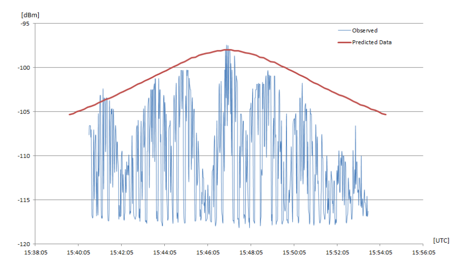
In his Individual Project in 2011, Fenglei Wu observed a number of passages of several CubeSats over Strasbourg, measuring accurately the signal strength as the satellite moved over the sky, tracked with the Ground Station antenna. The data obtained were obtained as described here. A typical plot of the signal strength from a pass of the XI-IV cubesat
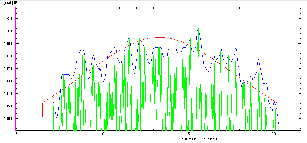
By carefully matching the observed signal strength profiles to the predicted curves, he was able to deduce the system gain that would result in a best match:
On 432 MHz, he found a station gain of +30.0 (+/- 0.7) dB, if he assumed that the XI-IV satellite had its nominal 100mW transmitter power, and +33 (+/- 0.8) dB from Cute-1 with its nominal 100 mW power. Obviously the actual powers of the two satellites differ! The difference of these values with the expected ones might be due to an error in the antenna position of 13° that existed during his measurement period.
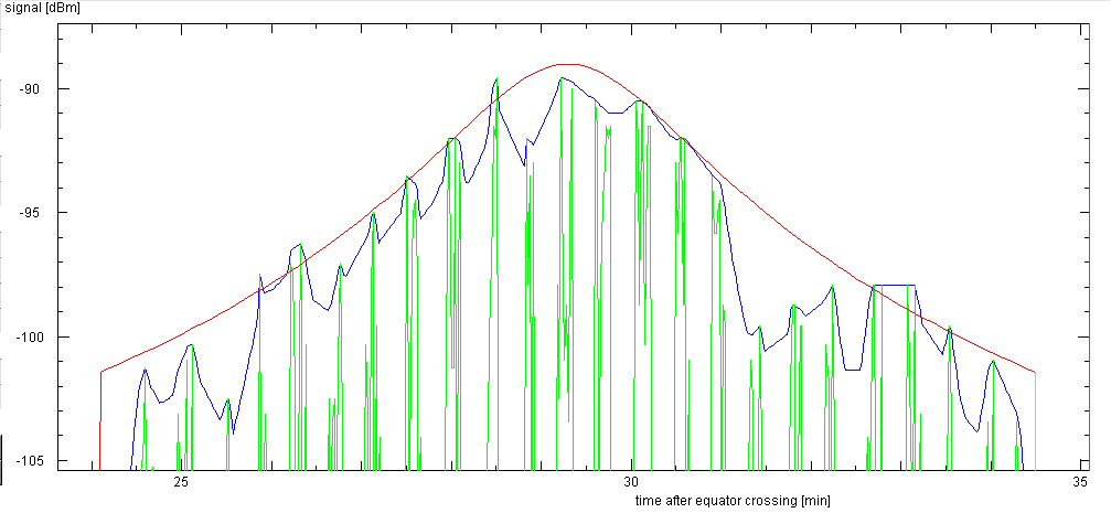
In the absence of definitive information about the real transmitter powers, and for convenience, we adopted a station gain of +31 dB. This value has also proven to give reasonable results with other satellites: like Cute-1 which now emits a nearly unmodulated carrier, but tumbles:
Since we have not been able to do similar measurements on 144 MHz due to lack of objects wth telemetry here, we have no measured value for the station gain.
| Top of the Page | Back to the MainPage | to my HomePage |
last update: Apr. 2013 J.Köppen