Filters for the RadioJove Receiver
Joachim Köppen DF3GJ Kiel/Strasbourg/Illkirch Summer 2003
This is caused by the very strong signals which occur under favourable ionispheric conditions. Though the signals are above 21.5 MHz, i.e. 1.5 MHz away from the listening frequency, the resonant circuits ahead of the mixer are not able to attenuate them sufficiently, so that the signals are directly rectified in the NE 602 mixer, an integrated circuit which cannot handle too strong signals.
It is not always a problem, because the propagation via ionispheric reflection changes with daytime, season, and solar activity. But if one is not aware of its presence, one might take some increase of the signal as a natural signal. Of course, direct listening of the audio output will tell the truth.
What can be done about it?
A narrowband filter in front of the receiver
A bandfilter with helical resonators for 20 MHz.
This option has the advantage that one does not need to change anything in the receiver itself. However, since any filter will give some attenuation of the signal, this will degrade the noise figure of the receiver, and thus limit the weakest signal which could be detected. This is not a big disadvantage as it might seem, since at 20 MHz noise from the Milky Way gives a background of about 50 000 K, while the internal noise of the receiver is about 1200 K. If the filter's attenuation is e.g. 10 dB, the galactic background is at 5000 K, still much above the receiver's noise. Thus it remains the limiting factor for detection of signals. Another disadvantage may be the large space occupied by the filter: In order to provide a large rejection to unwanted signals, the resonators must be of very low electrical losses, which unfortunately can only be provided by sufficiently large air coils.
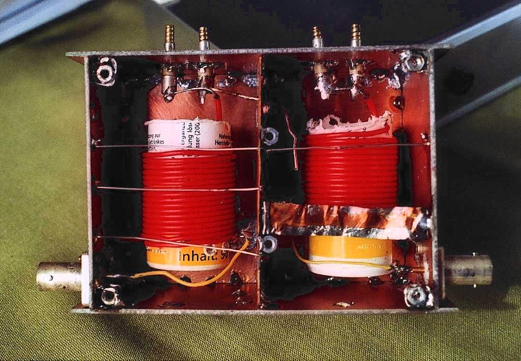
The best way to make low loss resonating circuits is to use helical resonators, i.e. the coils are in resonance with the capacitance of their shielding boxes.
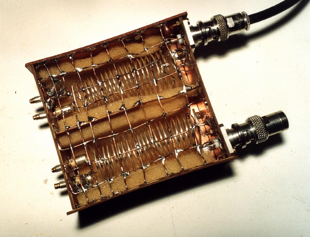
The filter shown above has two coils which are done from ordinary copper telephone or hook-up wire, about 0.5 mm diametre, with red plastic insulation, wound on 2.5 cm diametre plastic tubes. The hot end of each coil is terminated in a small trimmer capacitor. Since the trimmers I have are a bit jumpy when adjusting, I use two trimmers in parallel, each has 12 pF maximum capacitance. The two resonators are capacitively coupled via the silvered wire which leads from the top of the left hand coil through a hole in the partition and ends as a nearly vertical wire placed close to the top of the right hand coil. The input and output is done by a tap at 1/2 to 3/4 of a turn from the earthy end. The wires seen to bridge the front gap between the side walls are installed to electrically close the box as well as to shield the resonators from external influences. These wires are initially quite sufficient to close the box electrically while still allowing mechanical access to make adjustments e.g. of the coupling. Sometimes, an improvised close grid of wires can provide adequate shielding, as in the version we used in summer 2003 shown below. However, if you are in an electronically noisy environment, for instance next to computers, a complete screening is absolutely mandatory - after finishing the design, the filter was covered with a piece of sheet metal soldered over the compartment, and it is now literally watertight!
The above sketch shows the schematic structure of a helical filter with inductive coupling via an aperture in the central partition at the earthy ends of the coils.
Instructions how to design filters may be found in the book "Filter design and Synthesis" by A.Zverev. Here are some constructional details of filters I've built: The boxes are done from copper-clad printed circuit board; the size should be as large as convenient, but boxes with a square section of 4 to 6 cm , and about 10 cm height give reasonable results. The coil's diameter should be one half of the width of the box. Most often I use silvered copper wire of 1 mm thickness, but as shown in the filter above, normal copper wire also is useable. One makes as many turns as possible - ideally, the length of the coil's wire should be one quarter wavelength, but at 20 MHz that much of wire would not fit in the enclosure. The exact number of turns is not so important, since one will make the resonator resonate on the proper frequency with the trimmer capacitor. Sometimes, one needs to add a fixed capacitor as well.
Having built the two coils, next comes the most essential and critical part: The tuning of the resonators and the adjustment of the input and outputs and the coupling between the resonators. The possibility of displaying the filter curve while sweeping through the frequency is almost indispensible! One may tune the two coils to resonance by using a dip-meter. But swept frequency mesurement is the only way to adjust the coupling between the coils to the desired critical coupling, with a single maximum, a flat pass band and steep skirts. The input and output are connected to a very low tap on the coils, say to about one turn from the earthy end. This essentially sets the bandwidth of the filter. If desired, proper measurents of the bandwidth can be made to verify whether the desired value is obtained. For RadioJove applications, one wants to have some 300 kHz bandwidth, so that the receiver's entire tuning range fits in. If possible, one should measure the insertion loss, i.e. the attentuation in the centre of the passband. For the filters described here, about 3 dB should be expected. But note that even 10 dB will not severely affect the senstitivity of the receiver, due to the galactic background.
For the filter shown, the following passband curve was measured. The insertion loss at the centre frequency is about 3 dB.
| dB | f(MHz) |
| 0 | 20.10 |
| -3 | 19.95 ... 20.19 |
| -10 | 19.86 ... 20.29 |
| -20 | 19.62 ... 20.46 |
| -30 | 19.14 ... 20.73 |
| -40 | 17.86 ... 21.15 |
| -50 | 15.66 ... 22.27 |
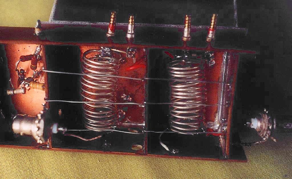
A helical bandfilter for 45 MHz. The red plastic wire provides the capacitive coupling.
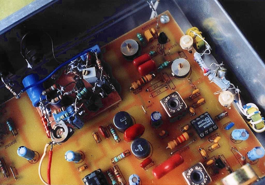
The filter's two toroidal coils are placed in the gap between the printed circuit board and the side panel of the enclosure, on the right hand side. The two trimmer capacitors are placed at the rim of the circuit board. Note that the three resistors between the r.f.amplifier and the mixer coil are removed.
The filter in front has several disadvantages: One needs a separate and may be large box, and it is necessary to use the proper measuring equipment to adjust and tune the filter. All this can be circumvented if one is prepared to alter the receiver. A good place to add selectivity to the set is between the FET r.f. amplifier and the mixer, since it is the mixer that needs protection against strong signals. In the original circuit, there is an attenuator with three resistors just in front of the mixer coil. It attenuates the signal by 3 dB. We insert instead of it a narrowband filter, whose midband attenuation does not need to be so low as for the filter in fornt of the receiver. Such a filter can be constructed easily using two coils wound on iron dust toroid cores. This permits to make rather compact but low loss coils, which are also quite insensitive to external influences. So they can be placed next to metal parts, like the enclosure.
The filter was designed to provide a rejection of about 40 dB at 1.5 MHz away from the centre. For a Butterworth response (i.e. critical coupling) a two-resonator filter would need a 3 dB bandwidth of 0.3 MHz. This loaded Q = 70 is 2.9 times lower than the unloaded Q = 200 measured for a coil, and thus an insertion loss of 5.5 dB is expected. The coils are 12 turns on Amidon T 50-6 iron dust toroid cores, with the input and output via a one-turn coupling. The capacitance necessary for resonance at 20 MHz is about 90 pF, which is done with a 20 pF trimmer (as available from the junk box) and additional fixed capacitors. From swept frequency measurements it was found that a capacitor of 3000 pF (polystyrene) would provide the desired coupling between the two parallel resonant circuits. The measured filter agrees with the expected filter curve, down to 50 dB attenuation, and the insertion loss is 6 dB.
measured response (t.b.d.)
The filter is inserted between the FET r.f. amplifier and the mixer coil. First, remove the attenuation pad (resistors R2, R3, and R4). Then install a resistor of about 150 Ohms to replace R2. This resistor will decrease the gain of the r.f. amplifier and thus help to keep the receiver stable. Connect the filter's input to the 'hot' end of this new R2. The filter output is connected to small track on the board where C9 and C10 are joined - you may remove the jumper 8. Then simply peak the filter's trimmers as well as trimmers C6 and C2 for maximum noise from the front end (place a 50 Ohm resistor across the receiver's antenna input, as described in the assembly instructions). Now tuned C2 through its entire range: if the receiver's noise shows a gentle peak at one position, all is o.k.; and you might try to remove R2 altogether. But if the noise changes abruptly, the r.f. amplifier's gain is too large and the receiver does not operate in a stable way. Then you have to put in a smaller resistor for R2.
With the generally available Amidon toroid and with the fixed coupling capacitor one can reproduce the design without difficulty. Tuning of the two coils is easily done by simply peaking both trimmer capacitors to maximum response.
The filter's insertion loss is larger than that of the helix filter above. The higher attenuation is the price for a much more compact filter! However, this does not degrade the receiver's performance: since the filter is preceeded by the low noise r.f. amplifier, the noise figure of the receiver is only 2 dB worse than the unmodified RadioJove, and 1 dB better than with a helix filter in front...
In the circuit diagram above, the transistors can be any general purpose silicon npn transistors (BC107, 2N2222). Likewise, by reversing the polarities one can use any pnp transistor.
The trimmer potentiometer sets the audio level for the computer.
| Top of the Page | back to Main Page | back to my Home Page |