The Loaded Loop Antenna
Joachim Köppen DF3GJ Kiel/Strasbourg/Illkirch Summer 2003
In case you want to set up an antenna but you don't have much space, take some plastic insulated copper wire, and make a simple dipole:

This will resonate at about 25 MHz. The feed point is either done with ferrite rings around the coax cable or a balun transformer is employed to make the transformation from the balanced antenna to the unbalanced cable: it consists of of wrapping about 4 turns of primary and secondary intimately around a small ferrite rod:

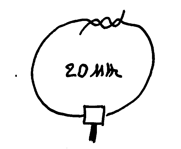
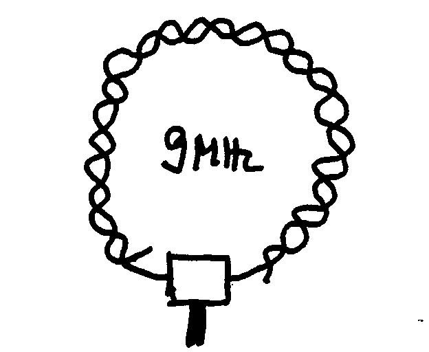
Now form a nearly circular loop (the exact shape is not very important), bringing the ends together and twisting them together, which forms a small capacitor. This additional capacitance in the antenna will lower its resonant frequency. Depending on the amount of overlap, and how tightly the wires are wrapped together, the resonance can be shifted over a wide range:


The antenna on the left may resonante near 20 MHz, while the fully overlapping loop at the right tunes to about 9 MHz.
This results in the lower frequency antenna to be physically smaller, which seems to contradict our expectations about antennas ...
The resonance frequency can be found simply by listening with the receiver to the external noise and signals, and monitoring the signal strength. (Thus you have an advantage if you live in an electrically noisy environment ...) Touching the antenna with your hand or changing the amount of the overlap of the wires may make the signal become stronger or weaker. By systematically changing the overlap, you can find a configuration of maximum signal strength, i.e. when the antenna is resonant.
| Top of the Page | back to Main Page | back to my Home Page |