SmithScope: displaying r.f.impedance directly in a Smith Diagram
Joachim Köppen DF3GJ Kiel/Strasbourg/Illkirch Summer 2003
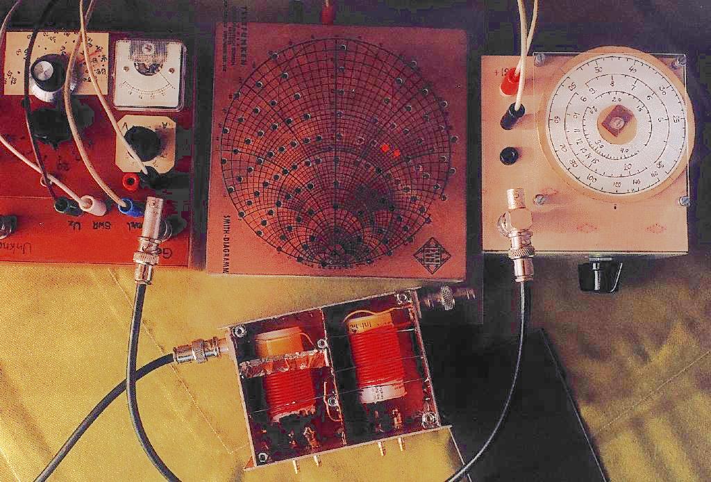
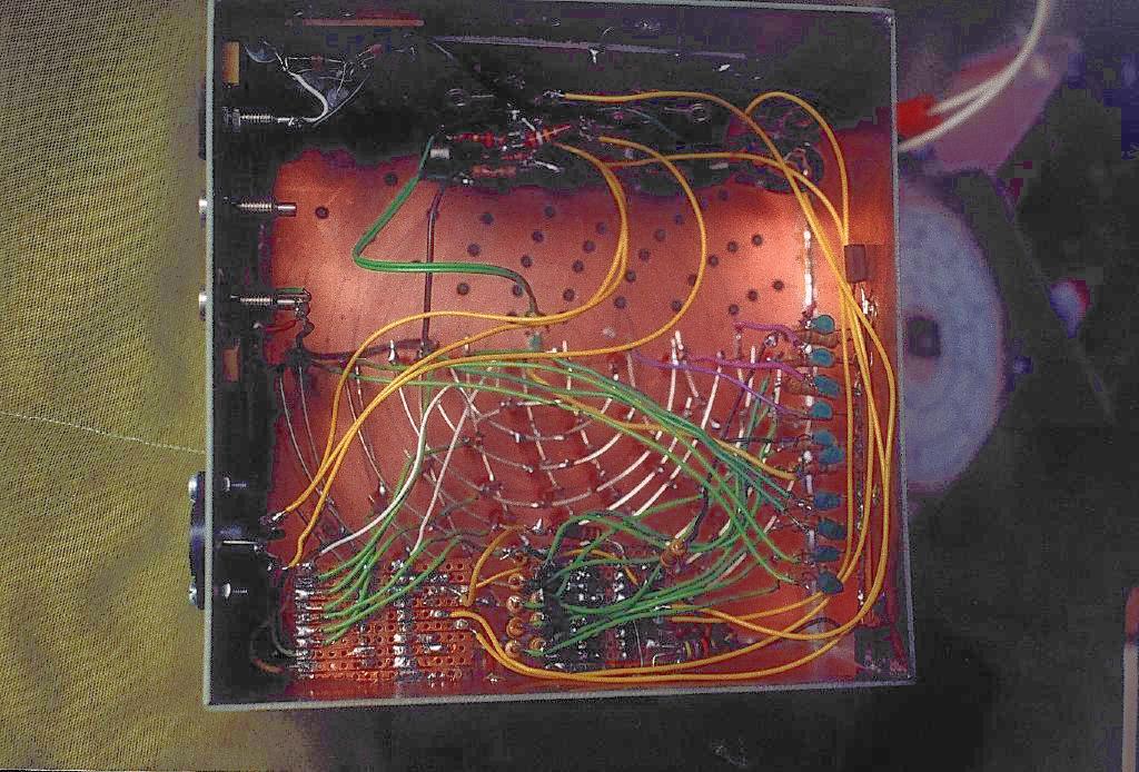
The SmithScope
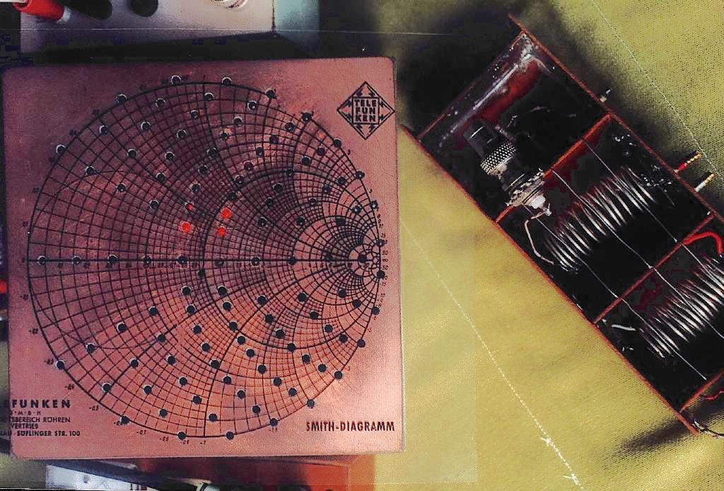
Narrow band helical filters
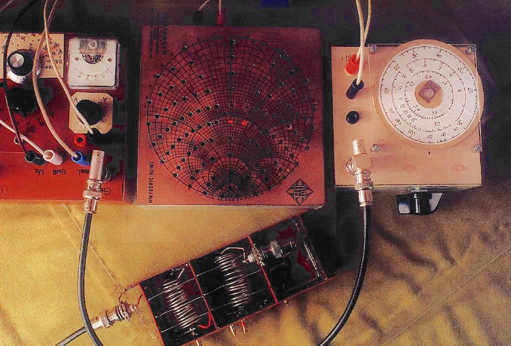
The same as above, but for a filter designed for 45 MHz.
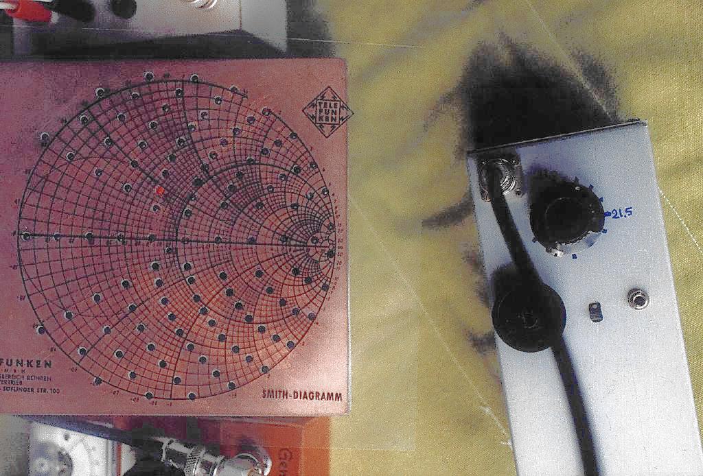
The impedance at the centre of the passband of the 45 MHz helical filter. Note that the transparency with the Smith diagram had been placed 180 degrees rotated from its proper position. One can also directly read off the VSWR of about 2:1, from the relative distance of the lit-up LEDs from the centre.
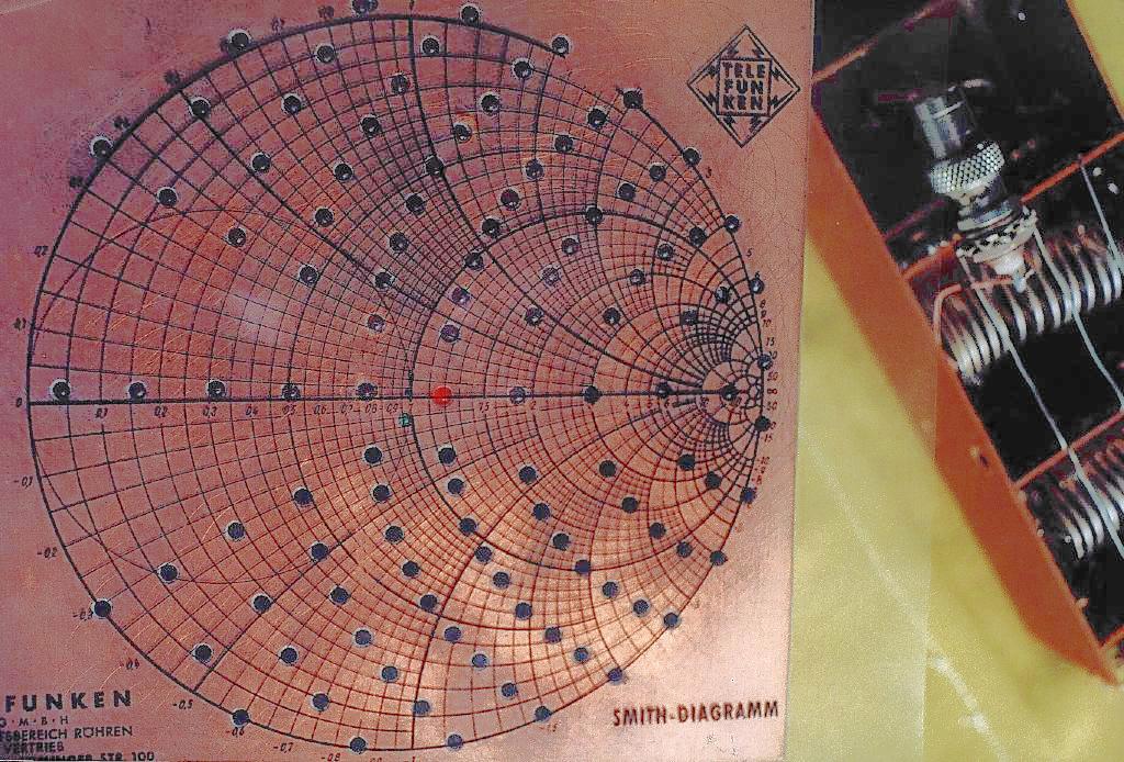
This is a further close up, at the frequency of the best match to 50 Ohms. Note that the green LED near the centre is lit in order to indicate that.