Noise Meter
Joachim Köppen Kiel 2018
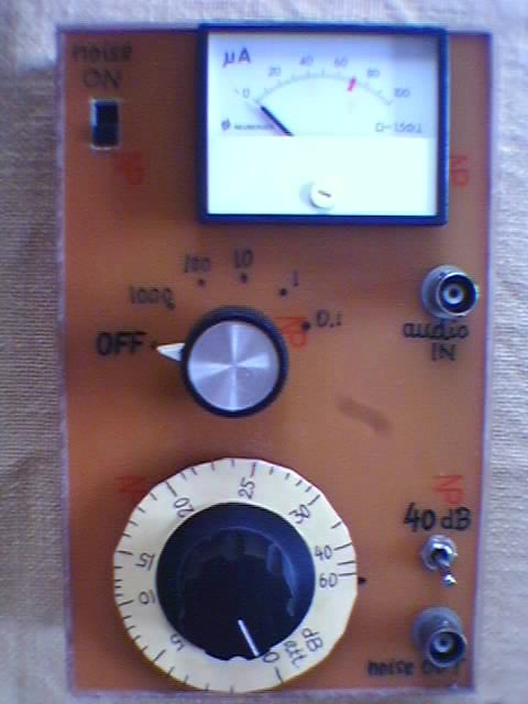
| This picture shows the completed instrument: it consists of a sensitive audio millivoltmeter whose range can be adjusted in steps between 0.1 mV and 1000 mV (seen in the top half), and an audio frequency noise source whose amplitude can be varied by means of a finely calibrated attenuator, covering attenuations between 0 and 60 dB (i.e. between no attenuation and a factor 1000000 in power) and another 40dB (factor 10000) with a toggle switch, all in the bottom part. The instrument has about the same size as the VLF-3 receiver. |
|
Here is a detailed description of the circuit and how it works.
The operational procedure is straightforward:Apart from comparing different receivers, we may also determine the absolute level of the internal noise. The VLF-3 has about 100ÁV internal noise, when the input low-pass filter is switched in, and about 1ÁV when it is switched out. Would one then leave the filter switched off? Not in the places where I live and work, because of the presence of strong AM radio stations in the medium and long wave range. If I leave the filter out, I can directly hear these stations much louder than any spherics! For a 1.5m long whip antenna, spherics come at a level of about 1 to 10 mV, quite far above the noise level; whistlers are often somewhat weaker, but signals at night are substantially louder.
The neat good thing about having a noise source is that we now have a signal available for receiver tests, with a strength similar to what we like to observe, but it is on our table ľ we do not need to take our receiver out to our quiet testing spot every time we made a change or an adjustment to the circuitry. Furthermore, the signal is constant, so that we can compare the receiverĺs performance, and we no longer are subject to the spherics level changing from day to day. This is a great help when building or modifying a VLF receiver.
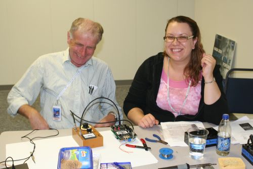
In summer 2009, the instrument had the opportunity to make itself very useful. We tested all the 10 receivers which the students had built. While my own VLF-3 would need an attenuation of about 65dB, any receiver which would require a value between 60 and 70 dB would also pick up well spherics when tested outside. However, there was one which needed 22 dB, and another one 55 dB ů both showed plenty of hum signals when taken around in the room, but both fell completely silent when taken outside! A poor solder connection in the front end turned out to be the culprit. After reheating the connections, everything was fine!
We did encounter some problems: when testing the receiver inside the building ľ where hum and computer hash were abundant ľ some of these nasty signals entered the VLF-3 receiver directly, because the circuit in its plastic enclosure has no benefit of shielding. Thus, our measurements might not be too accurate, as one could hear those sounds with no antenna attached!
| Top of the Page | Back to the MainPage | to my JavaScript Tools | to my Java Applets | to my HomePage |
last update: Apr 2018 J.Köppen