NASA INSPIRE's VLF-3 Receiver
Joachim Köppen Kiel 2018
A very good receiver, for which a kit is available, is the VLF-3 from the INSPIRE project:
|
|
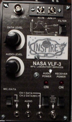
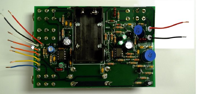
| VLF-3 outside view | VLF-3 circuit board |
This receiver has been used for several years during Summer Sessions of the International Space University. Here, a group of students - between 6 and 20 in number - were to build the receiver, make it work, and then set out to explore the universe of radio emissions at these low frequencies. For them it has been an interesting and challenging task to build a fairly complex electronic gadget (yes, we had lawyers, and they succeeded...!), to learn how such an instrument works, and then listen to natural and human-made radio noise.
In my experience, these kits - along with the informative materiel that accompanies it - provide an ideal opportunity to run activities for a group to get hands-on experience to make some hardware (and thus learn how to do a careful job). This device enables them to explore an unknown world, because we do not have a sense to radio signals. This also teaches them how one has to be patient with the reality of real observations!Here is a description of our activities.
The instructions for the VLF-3 are fine, but it is much safer to use a more systematic approach to assemble the kit: If you put everything together and then switch on the completed device, it can be frustratingly difficult to find the small mistake that prevents it from functioning. It is much better to assemble one section only and test it before starting on the next module, because then the fault can only be in the newly constructed part!
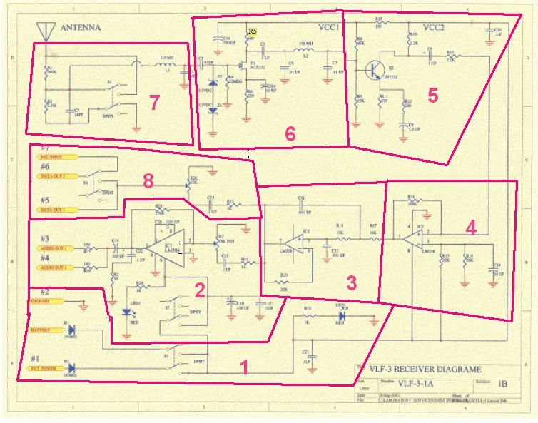
A logical way is to break down the total circuit in a number of modules or sections, each of which performs a certain function of the whole instrument, but each of which can be easily tested. We start with the output audio amplifier, because this can be tested by listening to the output. When all the other stages are added, we can monitor the progress, as the output signal would become stronger after each stage is added. Thus, we also do not need sophisticated test equipment!
Here are our preferred assembly instruction.
The modules are identified in this circuit diagram:
From our experiences two changes in the circuit are suggested:
| Top of the Page | Back to the MainPage | to my JavaScript Tools | to my Java Applets | to my HomePage |
last update: Apr 2018 J.Köppen