Photometry with Light Dependent Resistors
Joachim Köppen DF3GJ Kiel/Strasbourg/Illkirch May 2004
(I/I0) = (R/R0)^(-gamma)
where R0 is the resistance at the intensity IO. The constant gamma is given in the data sheet of the device, and is usually around 0.6 ... 0.8.
For our application, it is not necessary to have an absolute measure of the light intensity. We want to know how much the light at height h has diminished with respect to the value on the Earth's surface
I(h)/I(0) = (R(h)/R(0))^(-gamma)
Since gamma is a positive number, a drop in intensity always means an increase of resistance. And once we know gamma, we can compute intensity ratio from the resistance ratio.
How does one measure colour? By comparing the light viewed through a colour filter, say green (G), with the intensity obtained without the filter, i.e. in white light (W):
I(G)/I(W) = (R(G)/R(W))^(-gamma)
If the light source emits only green light, all of which will be measured both without and with the green filter, and the green resistance will be nearly the same as the white resistance, or a bit higher, because the green filter may absorb some light. If the light source emits in the red, the green filter does not pass anything, so the resistance with filter will be much higher than without... So the ratio of the green and white resistances gives a measure how green the incoming light is. And so on with other filters.
Again, if we know gamma, we can express this in intensity ratios. But as the passbands of the various filters are not perfect and absorb in a certain wavelength range, such knowledge would only be of use, if we knew the exact wavlength dependences of the filters, and if one wanted to compare the measurements quantitatively with model predictions. However, for a relative judgment of how the colour of the sky changes with height or with conditions, it suffices to calibrate such a photometer with light of various colours and keeping a record of the resistance ratios.
How to determine gamma
It is useful to determine the LDR's constant, because this allows to measure intensities, and one can also select devices with similar characteristics to combine them when building a multichannel photometer.
The first problem is to find a way to change the intensity of a light source in a quantitative way: As we have no calibrated light source of variable intensity at our disposition, we chose this two-step approach:
The picture above shows a piece of grey plastic I found on a flea market (left). To the right is a bundle of 10 grey plastic sheets, which are arranged to show - from top to bottom - 1, 2, 3, and 4 layers. It can provide attenuations from 1 to 10 sheets. Since each sheet attenuates by about 3 dB, one can thus cover up to 30 dB, which is a factor 1000 in intensity!
For example, here are the data (resistances in kOhm) of measurements taken with some grey plastic file and three LDRs like the ones to fly:
| No.of sheets | R_1 | R_2 | R_3 |
| 0 | 0.58 | 0.58 | 0.59 |
| 1 | 0.96 | 0.91 | 0.90 |
| 2 | 1.53 | 1.48 | 1.44 |
| 3 | 2.55 | 2.44 | 2.22 |
| 4 | 4.15 | 4.02 | 3.56 |
| 5 | 7.05 | 6.54 | 5.56 |
| 6 | 11.7 | 11.17 | 8.66 |
| 7 | 19.2 | 18.6 | 14.0 |
| 8 | 31.5 | 30.3 | 21.8 |
| 9 | 50.7 | 47.8 | 32.9 |
| 10 | 81 | 79 | 51.2 |
The reader may verify himself that the logarithm of ratio of two measurements with one sheet added remains constant, thus the LDRs do obey the power-law relation.
From this table it is already evident that the first and second LDRs are very similar, but that the third one gives lower resistances at low intensities.
How to measure the attenuation of the grey filter (I)
The next step is to measure the attenuation factor f of a single sheet: here we MUST attenuate the light by a specified amount... A simple method is to use the fact that the LDR have only a slow response time, of about 30 ... 50 ms. If one places in front of the LDR a fast rotating disk into which one has cut out a certain sector, say 36 degrees, the LDR will receive on the average only 10 percent of the incoming light. I used a cardboard disk with a variable opening, fixed into the holder for a small grinding disk and to be rotated by a small electric drill:
The following table gives measurements done with the first LDR whose resistance without the disk was R_360 = 0.58 and 0.5 kOhm in two sequences of measurement:
| angle | intens.ratio | R | R/R_360 | gamma |
| 90 | 0.25 | 1.70 | 2.88 | 0.76 |
| 72 | 0.20 | 1.62 | 3.24 | 0.73 |
| 45 | 0.125 | 2.95 | 5.0 | 0.76 |
| 36 | 0.10 | 2.82 | 5.64 | 0.75 |
| 22 | 0.0625 | 5 | 8.5 | 0.76 |
| 18 | 0.05 | 4.8 | 9.6 | 0.75 |
The last column shows that the gamma derived
gamma = -log(intens.ratio)/log(R/R_360)
comes out quite the same from the different measurements, which also confirms that the method works.
With this knowledge of gamma of this one LDR, we can compute the attenuation factor of a single sheet as:
f_sheet = (R_one_sheet/R_no_sheet)^(-gamma)
which comes out to be 0.515 from the data above. We might work in decibels, like in electronics (-10 dB meaning reduction by a factor 10): Thus a single sheet attenuates by 2.9 dB, ten sheets by 29 dB, almost a factor of 1000. In this way, we now have calibrated array of our grey filters, and can use it to measure more easily the other LDRs etc.
Note 1: this method of course can be used to determine gamma directly ...
Note 2: this second step of a determination of gamma proper is not really necessary for colour measurements. The photometer may remain calibrated based on the set of grey filters only! One only needs to keep the grey filters, to make a proper calibration possible at some later time!
Note 3: after some refinements of the setup, measurements gave gamma = 0.91 +/- 0.01 and an attentuation factor of 0.58, corresponding to -2.36 dB for a single sheet... But here I show the results of my first tries.
How to measure the attenuation of the grey filter (II)
An alternative method is to use an exposure meter from photography: Since a change in one f/-stop corresponds to a factor two in exposure time, i.e. in intensity, we can measure the difference between a reading without and with one (or several) layers of grey filter. If one needs two layers to cause a change by one f/-stop, we know that they make an attenuation by 0.5 (or -3 dB), so one makes 0.707 (or -1.5 dB).
Selections of matching LDRs
To sort out LDRs with closely matching characteristics, it would not be necessary to measure the entire calibration curve for each LDR. If one has convinced oneself that the LDR can be characterized by the power-law with the same gamma over a wide range of intensities, one may measure the resistance ratios for a couple of grey filters, say: without one, with five sheets, and with ten sheets. One selects LDRs whose two resistance ratios agree sufficiently well.
Experimental Photometer
To measure the intensity of light coming from various sources and seen through various colour filters and to perform various tests of the principle, I built a photometer using a light dependent resistor (LDR). In front of the photosensor there is a filter wheel containing various colour filters, from high quality ones to sheets of transparent plastic that I happened to have lying about, and to filters I wanted to test. Here is a view of the interior:
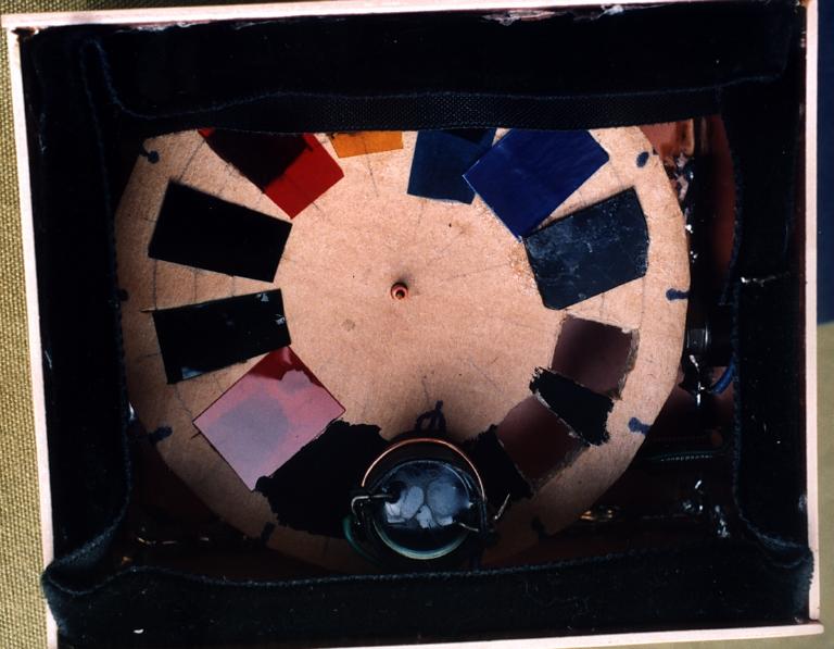
This photometer was used to make measurements from the ground of the sky above Kiel under various conditions.
The picture above shows another version of a photometer. It consits of a collimating telescope, made out of three black plastic film containers, which constitute a system of baffles in front of the LDR. This cuts down the straylight falling onto the LDR, which otherwise is reflected by the tube's sides from directions other than the desired field-of-view. The LDR is seen in the foreground, attached at the lid of one of the containers.
A Light Source
Also, I built another box, housing a cardboard wheel with a variety of light sources which one can use to make photometric measurements or look at with a spectroscope. It contains a small incandescent bulb to give 'white' light, an IR LED, and LEDs in the red, orange, yellow, green, blue, and violet. It is useful to check the wavelength region of colour filters, for instance to check whether a filter would let through all the light of a certain LED.
More experiments
are in work and conception...
| Top of the Page | back to Main Page | back to my Home Page |