The Flimsy AcceleroMeter: Main Body Construction
Joachim Köppen DF3GJ Kiel/Strasbourg/Illkirch Winter 2004
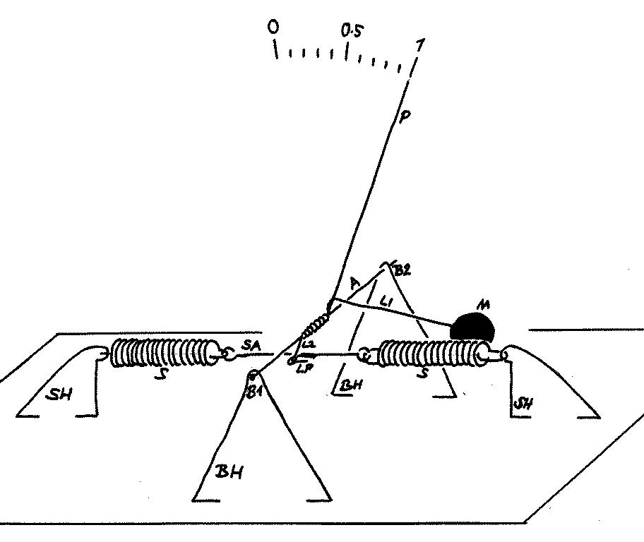
The device consists of two assemblies: the Spring Assembly and the Pointer Assembly:
Spring Assembly
It is best to start with the Spring Assembly: Make two identical triangular holders (SH) for the far ends of the springs. They are made from copper wire, which is strong and stiff enough to accept the springs force and also any reasonable shocks that the device will have to undergo. Solder the holders to the copper-laminated base plate. The dimensions are not critical, let the springs be about 10 mm above the plate.
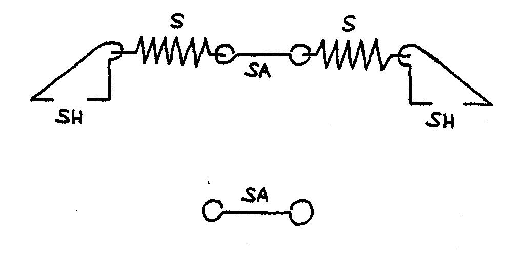
Make sure that each coiled spring has at each end a neat loop to join to. If your piece of spring does not have such a loop, grip the last turn of the coil with a pair of pliers and bend it gently but firmly into the desired shape.
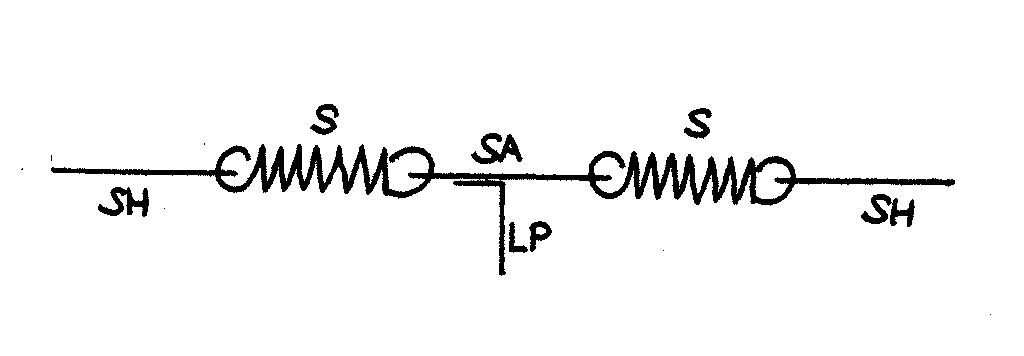
The spring assembly seen from the top. The linkage pinion LP is soldered to the spring armature SA.
In between the two springs there is a small piece of copper wire, the spring armature SA, with two small loops to accept the end loops of the springs. Its length could be about 10 mm, so that we can easily solder a small piece of copper wire to it. This piece should make a straight section of about 5 mm sticking out horizontally at right angles to the springs. This is the linkage pinion LP to which the pointer arm is attached.
Pointer Assembly comes next:
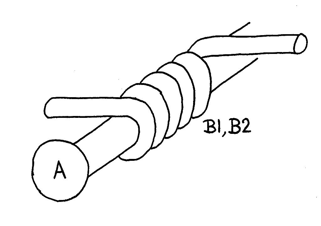
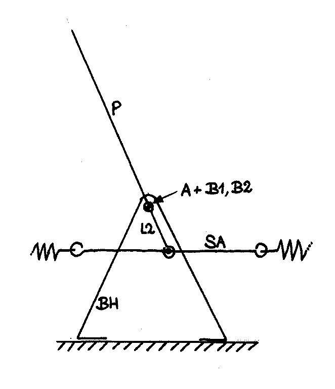
The pointer P with the arm L2 (made out of copper wire) rotates around a sewing pin (the axis A) which rests in two bearings B1 and B2 (each a small cylindrical coil of wire) which are held by two triangular bearing holders BH (of wire) soldered to the base plate.
About the Bearings:
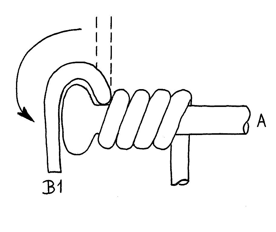
wrap a 20 mm long piece of wire (e.g. the leads of rejected semiconductor diodes) evenly around the sewing pin. Make about 5 to 6 turns and leave short straight pieces at the ends. One obtains a small coil of wire which fits more or less tightly around the pin. Gently untighten this coil until the coil can very easily rotate around the pin, without waggle.
For the bearing B1 which will hold the head end of the pin, bend the outermost lying end of the wire over the pinhead, so that the head rests securely in the small loop of wire. The pin should still be able to rotate easily!
The other bearing B2 remains a simple straight coil.
The pointer: take a long (150 mm) piece of copper wire, wrap it around the pin several times, also to make a neat, even coil that fits snugly around the pin. Also, loosen the coil just a bit, as to make the pointer to swing easily, but without a wobble, around the pin. At one end, leave a piece of straight wire of about 10 mm length; the other end you may make as long as you wish for the pointer.
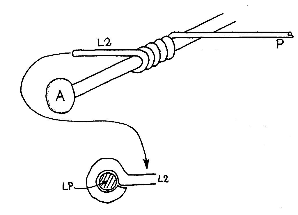
The shorter end will become the short arm L2: at a distance of about 3 mm from the pin axis, form a small round loop. Use the needle pliers to give it an initial shape, the compress it gently to get a closed, round eye hole. The inner diameter of this hole should be just large enough to accept the wire of the linkage pinion LP. The pinion should be able to move easily but without too much waggling.
The position of the pin axis should be above the armature between the springs, so that the pinion fits easily into the eye hole. Out of copper wire, bend two triangular shaped holders that can hold the bearings at that desired height. Solder the bearing holders BH to the base plate - place them in front of and behind the spring assembly so that on the side behind the springs there is a bit more space. The holders should be placed between the springs, where the armature is; the best position is the one which gives a pointer deflection of about 30 degrees off the vertical, when the springs are at rest.
Assemble the pointer, pin axis, and the bearings. Place them in position and solder first the bearing of the pinhead (usually facing the observer) by attaching the remaining bit of bearing wire to the triangular holder BH. Then do the other bearing, making sure that the pin axis is perpendicular to the springs and parallel to the base plate, and that the bearings also have the same orientation. Check whether the pointer will swing easily in its bearings, but that it stays well in its plane.
This part is a bit delicate and tricky. It may require unsoldering the holders in order to move them a bit to the left or right, so it is a good idea to make provisional solder joints first, and do the final soldering until after the most suitable position has been found! The bearings also may need a bit of bending and repositioning.
Now insert the linkage pinion LP into the eyehole, and if all is perfect, the short arm L2 and the pointer should be about 30 degrees off the vertical. This position is that of zero weight, i.e. 0 g. You can now bend LP so it does not slip out of the eyehole, as shown in the full view picture.
Next, install the sensor mass M. Under normal conditions (1 g) the mass should pull the pointer to a position of 30 degrees from the vertical, but on the other side. How far the pointer will swing under 1 g depends on the mass and the length of thhe arm L1. You'll have to play with these until you get a satisfactory result. The mass could be a small piece of metal - a coin, a nut, even a solder blob - or a small pebble which is encased into a tight-fitting wire frame... Try out the arm length to give a sufficient deflection. Then solder the wire arm to the pointer, close to its pin axle.
It is a good idea to make the mass in its 1 g position to hover just above the base plate. Then the latter forms a mechanical restraint for the mass, whenever the acceleration exceeds 1 g, for instance during the impact of the experimental box on the cushion.
One note: the pointer does not need to point upwards, as described above. As long as the short arm L2 swings over the range of $\pm 30$ degrees from the vertical, the pointer may be bent into any direction to furnish a convenient indication.
The picture below shows the heart of the machinery in more detail:
| Top of the Page | back to Main Page | back to my Home Page |