Notes and Tools about Paraboloidal Antennas
Joachim Köppen Kiel Dec 2022
Overview
Here is a collection of notes and links to JavaScript tools about paraboloidal
reflector antennas.
Hint: a click on an image will show it full size in a new tab.
-
Parameters of Aperture Antennas
computes the gain, half-power beam width, effective area and other parameters
of circular paraboloidal antennas, as well as the antenna temperature and
signal to noise ratio for a source of given radio flux and with specified
system temperature.
-
Antenna Patterns
are computed for square and circular aperture antennas, illuminated either uniformly
or according to some laws. This is done for a point source, which reveals the theoretical
pattern, as well as for extended sources of specified angular diameter and with
a few simple surface brightness distributions.
-
Performance of Parabolic Dish Antennas
is computed for illumination by various feeds. As in FeedPatt by W1GHZ,
the feed pattern, the antenna efficiency, spillover losses and illumination losses,
and the resulting antenna radiation pattern are calculated for dishes with specified
f/D ratio of focal length and diameter.
- The
Beam shape factor:
The Half-Power Beam Width (HPBW) of the antenna's main lobe is influenced by the
illumination of the reflector dish by the feed antenna. When the illumination
is tapered to the outer edge of the reflector - to e.g. -10 dB of its intensity
towards the dish centre - the main lobe becomes slightly wider, as the strength
of sidelobes and spill-over is reduced. The true HPBW can be computed from
HPBW = WF(taper) λ/Diameter
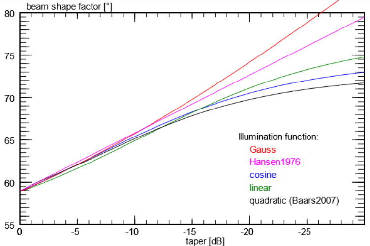
The plot below shows the dependence of WF(taper) on the edge taper for several
different illumination functions:

Quite interestingly, for tapers between 0 and about -15 dB, the actual shape of
the illumination function is unimportant. Thus, one gets the same results
for various illuminations, as long as the intensity ratio at edge and centre
is as specified.
The ratio b = WF(taper)/WF0 with WF0 = 58.95701° for
the uniformly illuminated circular dish, is called the beam shape factor.
For the quadratic illumination profile Baars (2007; The Paraboloidal Reflector
Antenna in Radio Astronomy and Communication, Springer) gives this analytic fit:
b = 1.269 + t*(-0.566 + t*(0.534 + t*(-0.208)))
with t = 10**(taper/20) and taper in dB.
The results of Hansen (1976; A One-Parameter Circular Aperture Distribution with
Narrow Beamwidth and Low Sidelobes, IEEE Transactions, Ant.and Prop., p.477)
can be fit with (and taper in dB):
b = 1.029 - 0.01195*taper
-
Antenna Spill-Over
computes from measurements of the sky noise at various elevations the
system temperature of the radio telescope and the zenith temperature for
the thermal emission of the Earth atmosphere. It then allows the user to
add spill-over noise to account for the enhanced sky noise measured at
elevations close to the zeinth. In this way, one can measure the
spill-over contribution to the system noise.
- Measures of the noise at
Sun Moon & Ground
along with the empty sky gives three estimates for the system temperature. Significant
differences between the values are a sign for errors in some of the measured values,
which indicates that the measuring methods or/and equipment need revision or improvement.
If the three values agree with each other, they very likely indicate the true noise figure
of the receiving system of antenna and receiver. This 'overall' noise figure includes also
how much noise from the surroundings is picked up by the antenna's side and rear lobes.
It thus gives an indication for the true efficiency of the antenna. Knowing this better
helps in optimizing the antenna system.
| to my JavaScript tools
| to my HomePage
|
last update: Dec. 2022 J.Köppen
