How to design a spectroscope
Joachim Köppen Kiel/Strasbourg/Illkirch Spring 2007
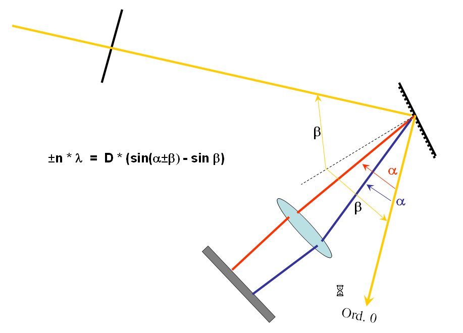
The basic geometry of a spectroscope is shown below: The light from the slit falls on the CDROM with an angle b with respect to the vertical on the CD.
The directly reflected light ("order zero") leaves the CD under the same angle
b, but towards the other side. Because
constructive interference at a wavelength
l occurs when
nl = D (sin(
a) - sin(
b))
we find on both sides of
the direct reflection the spectra of first, second etc. order.
The lens of our eye focusses the light beams coming from different
directions on different spots of the retina - in the same fashion
acts the lens of a camera when producing the image on the film or CCD.
In a normal spectroscopic instrument, the light from the slit is converted into a parallel beam of light by a collimator lens. In this way all the light enters the grating at the same angle, and hence one can make a most efficient use of the available light. If we make the distance from the slit to the CD relatively large, we could leave out the collimator. This makes the instrument somewhat less efficient, but much easier to build ... !
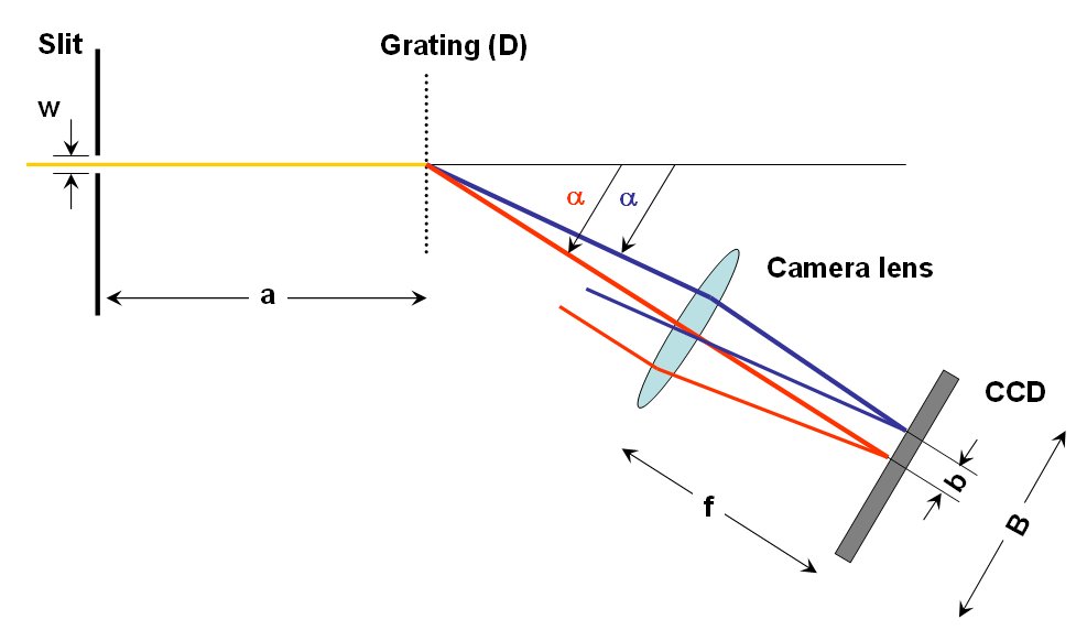
What are the best dimensions of the spectroscope? Let us consider the more simple geometry with a transmission grating, for which it is quite easy to work out the design:
From the grating relation for normal incidence
n l = D sin(
a )
we can obtain the dispersion of the spectrum:
n Dl
= D cos a(l) * Da
which tells by how much the deflection angle changes for a change in
wavelength.
For example, a CDROM has D = 1.6 µm, deflecting visible light by
about 20°. In first order, one gets a dispersion of
Da/Dl = n / (D * cos
a(l)) = 1/1.5 rad/µm
In other words, a wavelength range of 1.5 µm = 15000 Ĺ is spread out
over one radian.
The angular resolution limit of the human eye is about 1 arcmin, which is about 0.0003 radians. With a CDROM, a naked-eye observer would be able to resolve spectral features as close together as 5 Ĺ in first order, 2.5 Ĺ in second order, and 1.5 Ĺ in third order. This conforms well to my experiences that under optimal conditions (of direct incidence of sunlight, and a correspondingly narrow slit) the structure of the Mg b triplet (separations 5 and 10 Ĺ) is easily observed, and that the resolution of the Na D doublet (separation 5 Ĺ) is easily possible in second order, and sometimes even in first order.
The result of the passage through the grating is that the light of different
wavelength is directed into different angle. The objective of the camera
will focus all light coming from the same direction into a small spot in its
focal plane. This spot is displaced from the optical axis, the centre of the
detector (the eye’s retina or a CCD), by the following amount:
b(Da )
= f * tan Da
≈ f * Da
with the angle Da between the incident ray
and the optical axis. These two formulae together allow computing the
wavelength scale on the detector
Dl
= b_pixel * D * cos a / (f*n)
Here b_pixel is the size of one pixel or resolution element.
Furthermore, one can compute the wavelength range, given the size B of the detector:
l _2 - l _1
= B * D * cos a / (f*n)
Let us consider a normal webcam: the CCD is about B = 5 mm across, and has about 500 pixels. This gives a pixel size of 10 µm. The focal length of a typical lens is perhaps 5 mm, say. Using a CDROM as grating, one gets a wavelength scale of 30 Ĺ/pixel in first order, and 10 Ĺ/pixel in third order. This would mean that the yellow mercury doublet (separation 20 Ĺ) could not be resolved until third order. The first order spectrum of white light (4000-7000 Ĺ) would easily fit on the CCD chip and cover 100 pixels; in third order it would cover 300 pixels and thus still be covered by the chip.
If one substitutes the normal objective with a lens of longer focal length, such as the normal lens of a 24 by 36 mm camera – focal length 50 mm – the wavelength scale would increase tenfold: 3 Ĺ/pixel in first order and 1 Ĺ/pixel in third order – thus the resolution of the sodium D doublet could be done. Correspondingly, the wavelength coverage of the camera decreases: in first order, the CCD can cover only 1500Ĺ; and only 500 Ĺ in third order. Thus, provisions must be made for a rotation of the grating, if one wants full coverage of the visual range.
| Camera lens: | First Order: | Wavelength | Third Order: | Wavelength |
| focal length [mm] | scale [Ĺ/pix] | range [Ĺ] | scale [Ĺ/pix] | range [Ĺ] |
| 5 | 30 | 15000 | 10 | 5000 |
| 10 | 15 | 7500 | 5 | 2500 |
| 20 | 7.5 | 3800 | 2.5 | 1200 |
| 24 | 6.3 | 3100 | 2.1 | 1000 |
| 28 | 5.4 | 2700 | 1.8 | 890 |
| 35 | 4.3 | 2100 | 1.4 | 700 |
| 50 | 3.0 | 1500 | 1.0 | 500 |
| 100 | 1.5 | 750 | 0.5 | 250 |
| 135 | 1.1 | 550 | 0.4 | 190 |
| 180 | 0.8 | 420 | 0.3 | 140 |
| 240 | 0.6 | 310 | 0.2 | 100 |
Further considerations are necessary to ensure that these resolutions are indeed possible: The slit must be at a sufficiently large distance from the grating, to ensure a reasonable approximation for incoming rays to be parallel, so that one can do without a collimator lens. The camera lens then will be focussed not to infinity but to the distance of the slit. With the curved tracks of a CDROM, the best focus will differ from that setting, and it will depend on which side of the spectrum one choses, and on the wavelength.
The width of the slit is a strong constraint on the resolution: One may image that a
spectral line is nothing but the image of the slit projected into the detector. For a distance
a from the slit to the camera lens, we compute the angular width
tan Da = w / a ≈ b_pixel / f
Ideally, this angular width should be the same as the angle subtended by one pixel,
as seen from the objective.
However, one cannot make the slit as narrow as one should wish, because of the finite sensitivity of the detector, or the human eye. In the Muesli-box spectroscopes, a is about 25 cm. When observing the daylight spectrum with cloudy skies, one needs a slit width of less than 1 mm, hence the angular slit width is 0.004 radians, which is about 10 times worse than the angular resolution of the eye. With direct solar light available, the slit can be closed to 0.1 mm, which is still possible with cardboard construction, and thus one can take full advantage of the eye’s resolving power.
The above formulae and results are obtained in a simplified case. For reflection grating spectroscopes and non-normal incidence of the light on the CDROM, one needs to apply the proper geometrical corrections … while these will change the numerical values, the order of magnitude of the results can expected to remain the same.