The Radiation Pattern of the Antennas
Joachim Köppen Strasbourg 2013
The antenna is perhaps the most important element in a receiving system, because
its properties strongly influence the overall performance: The more strongly
the antenna's sensitivity is restricted to a narrow beam towards the source or
the other station, the better is its capability to receive only the desired
signal and to reject any signals coming from other directions: hence the better
is the signal-to-noise ratio.
The design of good antennas requires accurate measurement of the antenna pattern,
to verify that the theoretical calculations do indeed yield the desired properties.
Since the proximity of any material - such as conductors like metal structures or
the iron in concrete buildings, or the absorptive character of stone - can
strongly influence the antenna properties, measurements usually require to be
done on antenna ranges where the device under test is placed as far away as
possible from any such structures. However, the antenna in a real environment
will perform differently from such an ideal situation.
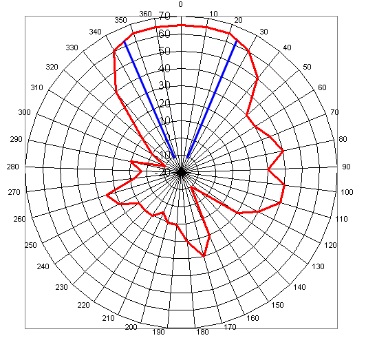
This is an early attempt to measure the horizontal pattern of the 144 MHz antenna
by observing the signal strength of an amateur radio FM repeater station in
Switzerland:
In his Individual Project in 2013,
Tingwei Guo measured the radiation patterns of the ground station's antennas
and compared them to the simulations based on an accurate modeling of the
geometry of the antennas. This is how he did it:
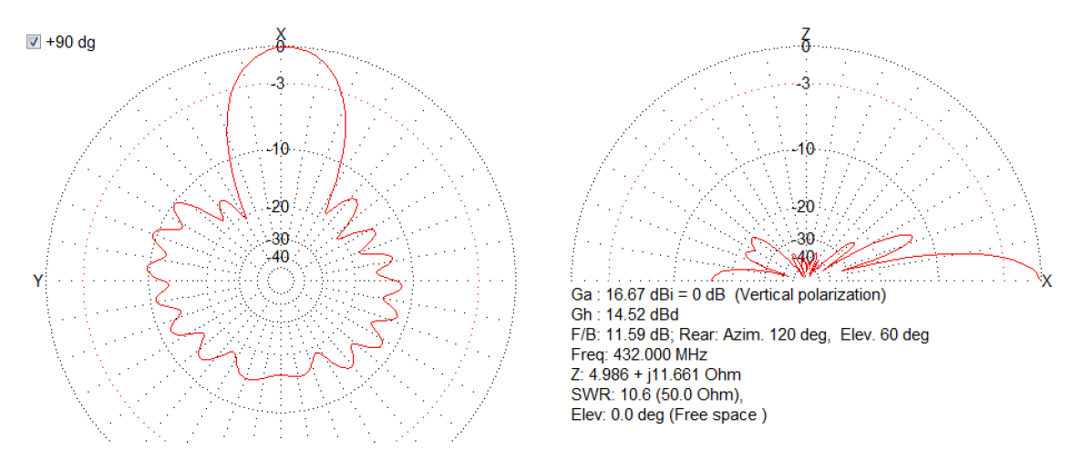
Simulation
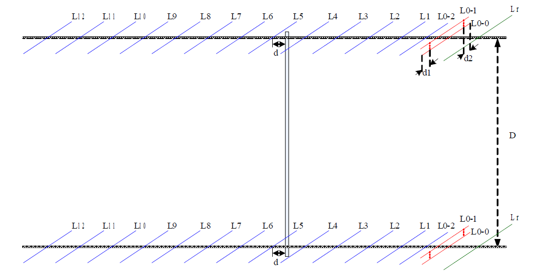
First, all the dimensions of the antennas were measured with a ruler and band
measure. This means all the lengths, diameters, and relative positions of all
the elements were measured. Here is a schematic drawing of the horizontally
polarized 432 MHz stack:
 These data were entered in the software MMANA-GAL
written by Macoto Mori, JE3HHT, a Japanese Radio Amateur and his friends.
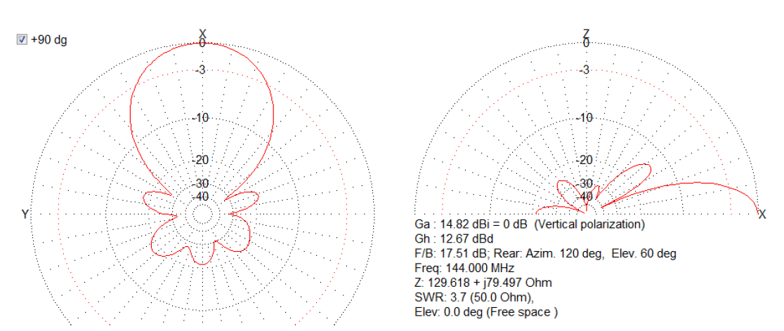
This program allowed to compute the theoretical patterns for the vertically
polarized 144 MHz stack:
These data were entered in the software MMANA-GAL
written by Macoto Mori, JE3HHT, a Japanese Radio Amateur and his friends.
This program allowed to compute the theoretical patterns for the vertically
polarized 144 MHz stack:
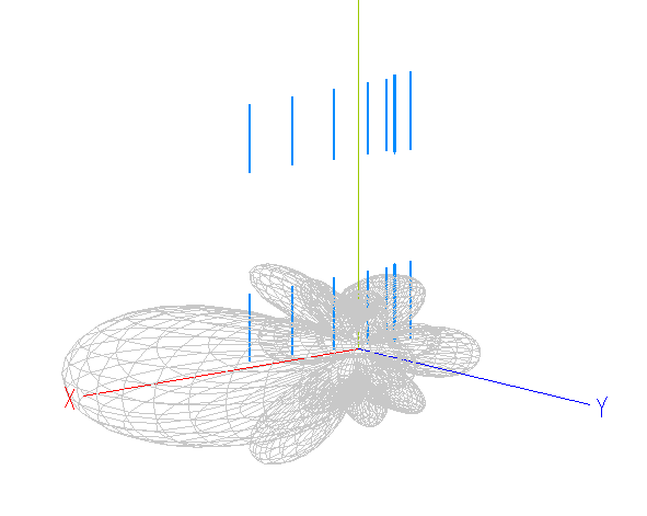
 which can also be shown in 3-D version:
 and the 432 MHz stack
Measurement
The next step was to measure the patterns:
- a signal generator was placed on the roof of the northern wing
- frequencies in the 144 and 432 MHz band were used. Since the distance
between generator and ground station is about 30 m, which corresponds
to 15 and 45 wavelengths respectively, we are well outside the
near field region.
- the transmitting antenna was simply a short vertical wire that was
put into the generator's coaxial output socket
- the generator's output power level was lowered sufficiently as not
to overload the receiver
- the transceiver was tuned to the correct frequency. In CW/LSB/USB setting
one heard a steady tone with a pitch of about 1kHz (a nice whistle).
- the Java software IC910Tester - as described here
was used to record the signal strength
- the antenna was turned in azimuth, in steps matched to the variations of
the signal. At each position, the constant signal level (in dBm) was
noted along with the position angle. The file which recorded the signal
strength measurements was later used to extract accurate average values
for each position.
- in the same way, the vertical pattern was obtained by raising the
antenna in elevation. This was done for the azimuth where the antenna
pointed to the generator as well as when it pointed in the opposite
direction. Thus both the front and the rear patterns were secured.
Comparison with Simulation
Comparing the measured and simulated patterns of the horizontal plane
showed that the primary lobes in both antennas were in excellent agreement:
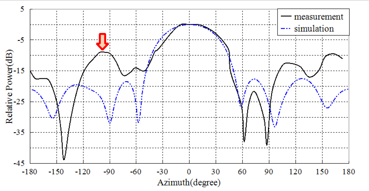
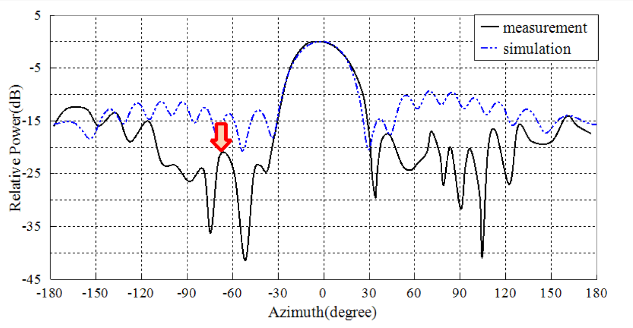 However, there were significant differences in the side lobes, although
there was a certain similarity, such as the positions of the nulls. In the
144 MHz pattern there was also a strong feature, as indicated by the red
arrow, which had no symmetric counterpart on the other side. The 432 MHz
pattern also exhibited an asymmetry ... This could be traced to reflections
of the radio waves from the generator by a tall vertical lightning rod in about
3 to 4 meters distance from the Ground Station antenna!
However, there were significant differences in the side lobes, although
there was a certain similarity, such as the positions of the nulls. In the
144 MHz pattern there was also a strong feature, as indicated by the red
arrow, which had no symmetric counterpart on the other side. The 432 MHz
pattern also exhibited an asymmetry ... This could be traced to reflections
of the radio waves from the generator by a tall vertical lightning rod in about
3 to 4 meters distance from the Ground Station antenna!
The patterns in the vertical plane also showed excellent agreement for the
main lobe, but strongly differing side lobes, both at 144 MHz:
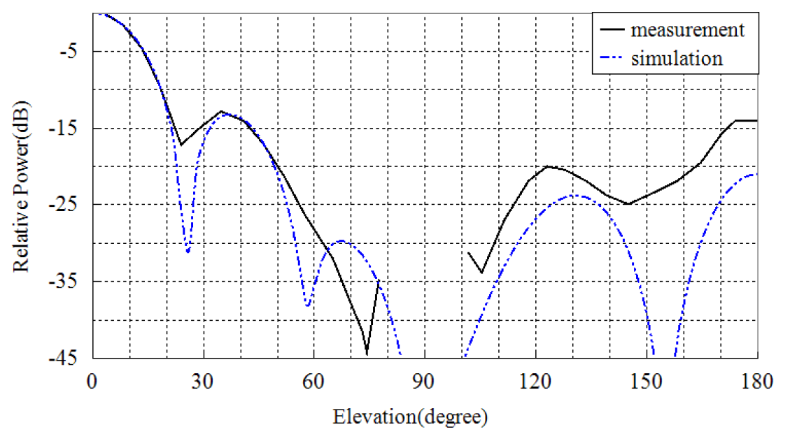 at at 432 MHz:
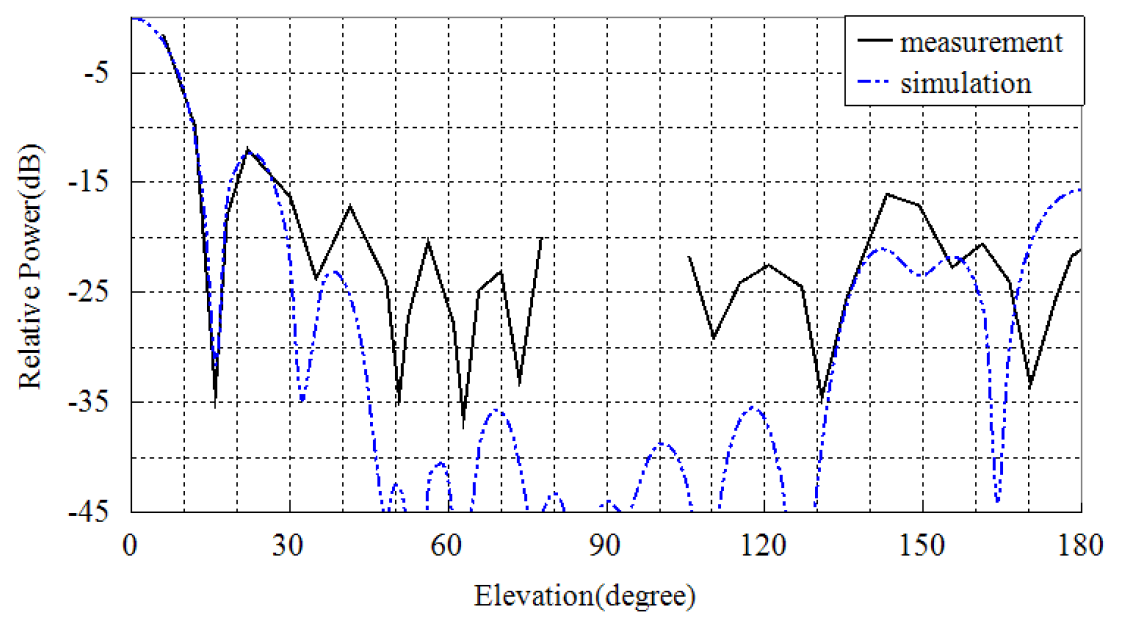 As there are quite a few metallic structures, like the railing and the floor
of the roof, as well as the platform on which the antenna is mounted, it is
very likely that this environment affects the side lobes.
As there are quite a few metallic structures, like the railing and the floor
of the roof, as well as the platform on which the antenna is mounted, it is
very likely that this environment affects the side lobes.
The characteristics of the antennas
Instead of specifying the detailed patterns, it is more convenient for
operations to look at the properties of the main lobe:
| HPBW | HPBW | Front/Back ratio | Front/Back ratio |
| antenna | H plane | V plane | simulated | measured |
| 144 MHz H-pol. | 46° | 22° | 20dB | -- |
| 144 MHz V-pol. | 56° | 22° | 21dB | 10dB |
| 432 MHz H-pol. | 26° | 14° | 17dB | -- |
| 432 MHz V-pol. | 28° | 14° | 15dB | 12dB |
Comparison with Theory
For a first estimate, we may use the simple formula between the antenna gain
and the HPBW valid for parabolic dish antennas:
HPBW = 180° / sqrt(10^(gain_dBi/10))
For the above example on 144 MHz, we know the gain of a single antenna by
12.2 dBi which gives 44°, close enough to our measurement.
Why do we compare the horizontal HPBW with that of a single antenna? Because
the two single 144 MHz antennas are stacked vertically: The resulting
horizontal pattern is equal to the pattern of the single antenna,
while the vertical pattern is narrower (about one half: 22°)!
| Top of the Page
| Back to the MainPage
| to my HomePage
|
last update: Apr. 2013 J.Köppen