The Dipole Antenna at ISU for RadioJove
Joachim Köppen DF3GJ Kiel/Strasbourg/Illkirch Summer 2003
The antenna is a fullwave dipole, consisting of a normal centre-fed half-wave dipole to which another half-wave section is attached via a phasing line.
This approach was chosen, since the space was available as well as the copper wire provided in the kit, and one could fed the antenna at low impedance (70 Ohm). Also, it was practical to start construction with a conventional dipole as described in the RadioJove instructions.
The antenna pattern of a half-wave dipole resembles a figure-of-eight, with the greatest sensitivity in the plane perpendicular to the dipole's axis. The field strength at an angle of theta to the dipole is proportional to cos(theta) Thus the dipole is least sensitive in the direction of its wire:
The opening angle of the pattern is defined as the angle between the directions at which the sensitivity has dropped to one half of the maximum value. If the dipole is in free space - thus neglecting any neighbouring building of ground - this angle is 90 degrees.
If one joins a second half-wave length of wire to the end of the first dipole, the two sections operate out of phase: the current distribution an one instant would be like this:
The two sections thus counteract in the radiation, and the resulting antenna pattern becomes a clover-leaf:
with minium sensitivity along the dipole's axis as well as at right angles to it.
If one introduces a phase shift of 180 degrees (corresponding to one half wavelength), at the joint, both sections can be made to work in phase, to have a current distribution:
The opening angle decreases to 50 degrees, and one obtains a "gain" of about 2 dB at reight angles to the dipole. Thus a signal from that direction will cause a greater voltage (by 25 percent) than induced in a half-wave dipole.
The phase shift of 180 degrees is obtained by connecting the two dipoles via a phasing stub of quarter wavelength. This is merely a piece of a twin-wire-line whose one end are joined to the dipoles while their other ends are joined together:
This twin-wire lead is stuffed into a plastic tube to make it more compact:
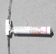
The antenna is fed in the way described in the Jove antenna manual, using three ferrite tubes to prevent waves travelling along the coax outer screen:
We note that the two antenna patterns are identical to the two possibilities described in the RadioJove antenna manual by connecting the two dipoles in phase or anti-phase.
But if one does neither have the space to suit either antenna, it is well sufficient to put up a normal half-wave dipole. Put it up as high as possible and as far away from houses and electrical lines as possible. You loose only a small amount of advantage by not being able to have a slightly more directive antenna!
But even if you haven't got the space to hang up a half-wave dipole, you can try a Loaded Loop Antenna.
| Top of the Page | back to Main Page | back to my Home Page |