Frequency [GHz]
TX antenna HPBW [°]
TX beam at X, Y [°]
RX antenna HPBW [°]
RX beam at X, Y [°]
TX fill factor:
illuminated:
TX-RX overlap:
received (BWF):
Offset loss:
analytical formula:
Mouse position:
Two Narrow Beams on the Moon
Joachim Köppen ... Kiel, Oct 2022
Some brief explanations
This tool shows the distribution of the radio power deposited on the Moon by the
beam of the TX antenna. It computes the power received by the RX antenna, while
both antennas may be pointed to different positions on the lunar disc.
It is based on the article Radar Studies of the Moon by J.V.Evans in
J.Res. National Bureau of Standards, Section D, p.1637 (1969)
(available at https://nvlpubs.nist.gov/nistpubs/jres/69D/jresv69Dn12p1637_A1b.pdf),
in particular on equation (2).
More details can be found here
The reflectivity of the Moon can be taken to be constant across the lunar disc
(default) or to vary with distance from the disc centre as estimated for
this frequency from measurements (derived from Fig.10 in Evans(1969), and other works).
Note that the radial profiles of the reflectivity are normalized to give the same
overall reflectance for the Moon, in agreement with measurements (Evans (1969) finds
a constant value 0.07 for all frequencies between 150 MHz and 35 GHz).
Since at lower frequencies the Moon reflects predominantly by the central part of the
disc, this produces a seemingly weird result that the received fraction may be greater
than the illuminated fraction ... But please keep in mind that these fractions do not
describe powers, but the overall brightness of the lunar disc.
The image of the Moon can be displayed with:
- illumination of the Moon by the transmitting antenna
- relative intensity of the reflected power
- relative intensity of the received signal
Please note that several features will become available only after the explanatory article appears in DUBUS.
Hit the Enter key after changing the value in one of the input fields, to show the new image.
The face of the Moon can be shown as a false colour image (the colour bar at right codes the relative intensity between minimum (black/violet) and maximum values (red)), which are either automatically adjusted or set by the user, or as a contour plot with the user-chosen values.
Please note that the HPBW usually should be larger than the pixel size in the image. Otherwise the program will take a minimum value for the HPBW in order to prevent computational problems. This is indicated by a light yellow background of the textfield.
Explanations in more detail
In Earth-Moon-Earth communications a signal is transmitted towards the Moon, all or some
part of which illuminates the Moon, from which some portion is reflected back to Earth,
where it can be picked up by the receiving antenna. The power PRX
can be calculated from the Radar Range Equation:
PRX = PTX GTX GRX
λ² A ε / (64 π³ d²TX d²RX)
with the transmitter power PTX, the gains
GTX, GRX of transmitting and receiving antennas,
the wavelength λ, the area A = π R²moon
of the lunar disc, the reflectivity ε of the lunar soil, and the distances
dTX, dRX between Moon and antennas.
The elevation-dependent attenuation by the Earth atmosphere at either end is neglected. Also, for all the derivations below, the lunar reflectivity is taken to be constant across the face of the Moon. Since the radial distribution of reflectivity varies with frequency, this assumption results in frequency-independent expressions which capture the essential effects. Please note that the JavaScript tool has the option to compute the results with the radial variation of reflectivity for the given frequency.
However, the above equation assumes that the beams of both antennas are much wider than the
Moon, and that both antennas are well directed on the Moon, so that the lunar disc is evenly
illuminated and the signals from every part of the disc are picked up with the same sensitivity.
But if the antenna beam widths are comparable to or even smaller than the angular diameter of
the lunar disc, there is an additional factor which takes into account how well the antenna beams
cover the Moon as well as each other:
BWF = ∫ ΦTX(x,y) ΦRX(x,y) dx dy / (π R²moon)
which may conveniently be called the Beam Width Factor.
The antenna patterns may well be approximated by 2-D Gaussian functions:
Φ(x,y) = exp(-(x² + y²)/(2 σ²)) .
The width parameter σ = HPBW/2.3548 = HPBW/ √(8 ln2) is related with the HPBW of the
corresponding antenna. The integral goes over the lunar disc
(i.e. x² + y² ≤ R²moon) and is normalized to the area
of the Moon's cross section.
Note that due to its diameter of only 0.5° the Moon is quite a small body in the
sky, and therefore we may well write the integral in the cartesian coordinates of the horizontal
and vertical offset angles from its centre.
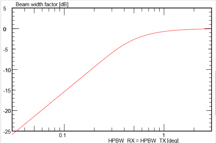
The beam width factor remains close to unity, as long as the beams are wider than the
Moon's angular diameter. With beams narrower than about 0.5° it decreases
as shown here, thus causing a loss of the received signal strength:
For a better understanding it is useful to split up the BWF into two factors:
BWF = illuminated(HPBWTX) * beam_overlap(HPBWTX, HPBWRX)
The first part is the illuminated fraction (displayed in the script):
illuminated = ∫ ΦTX(x,y) dx dy / (π R²moon)
It measures how much of the lunar disc is illuminated by the transmitting antenna.
An analytical formula with HPBW in degrees
illuminated(HPBW) = -10 log10( 1 + 1/(2.4*HPBW)² ) + 1.1 exp( -(ln(HPBW/0.8))² )
gives a good fit. Note that the illumination factor is quite different from the Moon's
filling factor in the transmitting beam, which is the fraction of beam power received by the Moon.
The second part is the beam overlap factor
beam overlap = ∫ ΦTX(x,y) ΦRX(x,y) dx dy / ∫ ΦTX(x,y) dx dy
It indicates the degree by which the transmitting and receiving beam patterns overlap on the
lunar disc. As before, all integrals are taken over the lunar disc. It is worth noting that
if both beams have the same width and smaller than the lunar disc, the overlap
factor is 0.5 for any width. Hence, having the same narrow beam in both antennas
alone is responsible for a 3 dB loss in the signal level.
An approximate analytical formula for the overlap factor can be given:
beam overlap(HPBWRX, HPBWTX) = a*(1-c) + b*c
with a = 1/(1 + (HPBWTX/HPBWRX)²),
b = 1/(1 + 0.17 / (HPBWRX)²),
c = 1/(1 + 0.035 / (HPBWTX)³)
The Beam Width Factor is well fit by this formula:
BWF(HPBWRX, HPBWTX) = a + b + c
with a = 1/(1 + 0.17 (1/HPBWTX² + 1/HPBWRX²))
b = 0.1 exp(- 10 (log10(HPBWRX/0.45°))² ) / (1 + 0.1/HPBWTX³)
c = 0.1 exp(- 10 (log10(HPBWTX/0.45°))² ) / (1 + 0.1/HPBWRX³)
With narrow beams it also becomes important, whether the two antennas are precisely
directed to the same position, as it is supposed for the above expression.
In this script we also allow that the centres of the beams are displaced against
each other. If we compute the beam width factor, but with a certain
offset angle δ, in the x-direction, for example:
BWF(δ) = ∫ ΦTX(x-δ, y) ΦRX(x+δ, y) dx dy
and then normalize it to the case without offset, we obtain a factor which
describes the loss due to the mis-alignment of the two antenna beams, and thus may
be called 'pointing loss', 'alignment loss', 'skewing loss', or Offset loss:
offset loss(δ) = BWF(δ) / BWF(0)
This factor is well described by the analytical formula
offset loss(δ)dB = -12 δ² / (HBPW²TX + HBPW²RX)
as long as the major part of the receiving beam remains on the lunar disc.
Thus, the overall link budget of the EME operation can be broken down into three
parts, which deal with different aspects. Written in decibel values, it is
this sum:
PRX dB = PTX dB + RadarRangedB
+ BeamWidthFactor(0)dB + OffsetLoss(δ)dB