Experiments with CD ROMs
Joachim Köppen Kiel/Strasbourg/Illkirch Spring 2007
On a sunny day, we let the sun shine on a CD and watch the colourful reflections on a screen of white paper or a wall. One can also a nice demonstration in the evening by shining the strong light from a projector onto the CD! The sketches show a few experiments that can easily be done. I have used half a CD, as this shows which part of the disk is responsible for which reflection image.
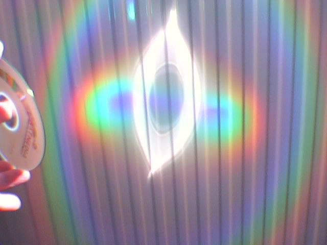
In the first experiment we observe that around the white image of the direct reflection there are two bright rainbows. When you use an entire CD, you'll get two concentric circles of colours. These coloured rings differ from genuine rainbows in that they are made by a different physical effect, although the colours are arranged in the same sense: violet is inside and red outside. Note that the smaller bow is on the opposite side of the larger one and of the direct image. If you look carefully, you will see a fainter set of rings further outwards.


The experiments can be done with any CD. The more shiny recordable ones (photo above) give much brighter rings. Below is a photo of the reflections from a normal CD:
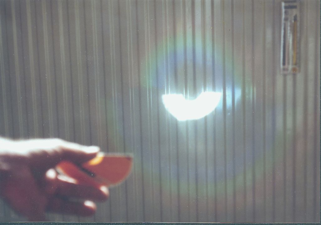
These photos are not entirely faithful to the colours: in reality the transition between the colours is much smoother! It is the colour filters in the emulsions of the photographic film that cause the sharper transitions. The same effect occurs in digital cameras or webcams.
If the sun is not shining, but if you have a laser pointer, you can do similar experiments, but all in monochrome red.
Now mask off the CD as to leave only a small portion uncovered, or use a small piece cut-off from a (smashed) CD. You will see that each ever-so-small piece produces two sets of coloured reflections, and that the direct image is just in the middle between them. So each portion of a CD behaves like a diffraction grating.


Because the tracks or grooves are arranged in a circular fashion, the "rainbow" reflected towards the centre of the disk is more compressed than the other. If we mask off the central region, we get this image
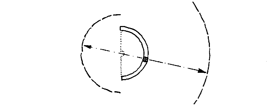
This shows that a small section of the disk produces two bits of "rainbow". If you vary the distance of the CD to the screen to about 15 cm, the inner ring is focussed into a small bright spot. Since also the various colours of the optical spectrum overlap, they combine to give almost the white colour. If we were to look at the CD with our eye placed in this focus, we would see spectra coming from the whole circumference of the CD! This is the reason for the spectacular view in the street-lamp experiment.
The data which represents the music is stored on the CD in form of very small pits arranged in a tightly wound spiral track in the silvery surface. The distance between two neighbouring tracks is 1.6 micro-metres which is only several times the wavelength of visible light, thus it is too small to be seen in a simple microscope. One needs a professional quality instrument at 1000x magnification:
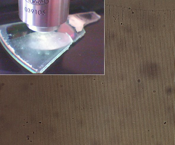
It is this narrow spacing that is responsible for the wonderful colours reflected by a CD which works just as a diffraction grating. Consider a small part of a CD (see the sketch) with light shining perpendicularly down on its surface: So all the grooves are illuminated by the incoming light wave at the same time. Each groove sends out a lightwave in all directions, and the outgoing wave is the result of the superposition of all these individual waves.
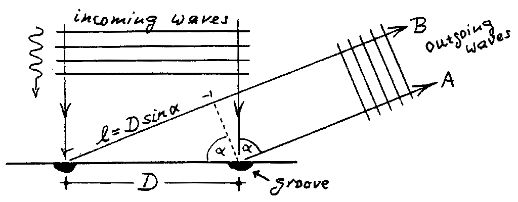
The light from the left groove in the sketch lags behind the wave sent out from the right groove, because its path is longer by the piece l = D sin(a). If this path difference equals one half wavelength (or an odd multiple) the peak of wave A coincides with the trough of wave B, and the two waves cancel each other. But if l amounts to one full wavelength, the peaks of the waves from neighbouring grooves overlap, and one gets a bright light in that direction. Since the separation of the grooves is the same everywhere on the disk, the contributions from all grooves assist each other. This is the first-order spectrum. The second-order spectrum is formed when l equals two wavelengths, the third-order arises from l = 3l, and so on.
This means that we get a strong reflection from the grooved surface only in the direction sin(a) = l/D (or any multiple of l/D). Because this direction depends on the wavelength, it is possible to build spectroscopes with diffraction gratings. For the CD we know that D = 1.6Ám, and we can compute the deflection angles (a) for each colour of the (first order) spectrum:
| CD ROM | DVD | ||
| colour | wavelength l(nm) | deflection | angle a(deg) |
| red | 650 | 24 | 61 |
| orange | 600 | 22 | 54 |
| yellow | 575 | 21 | 51 |
| green | 550 | 20 | 48 |
| bluegreen | 500 | 18.5 | 42.5 |
| blue | 450 | 16.3 | 37.5 |
| purple | 400 | 14.5 | 32.7 |
In a DVD the tracks are even closer together (D = 0.74Ám), hence the deflection angles are much larger.
The accurate measurement of the angle allows to measure the wavelengths. We note that the angle increases almost linearly with wavelength. So we may estimate the wavelength of a colour or line simply by judging its distance to certain known colours, such as the orange Na D line at 590 nm, or the lines of Mercury: 579 and 577 (yellow), 546 (green), 436 (blue), and 405 (purple).
The "rainbows" you saw from the CD in the sunshine are the first order reflections (one wavelength path difference between neighbouring beams), in the centre there is the zero order image, and the fainter bows further out are the second-order spectra.
With a CDROM one may use any of the orders up to the fourth one which has a deflection angle of about four times 20░ of 80░. You will notice that the first order is the brightest, and that the higher orders are progresively fainter. However, the advantage of the higher orders is that the spectrum is spread out over a larger range of angles, thus the second order spectrum is twice as wide as the first order. This makes it possible to distinguish spectral lines better, despite the darker spectrum. As the spectra get wider with increasing order, they overlap: for instance the red part of the second order is superposed on the third order's violet part: the wavelength of 400 nm in third order gives the same path difference as the wavelength of 600 nm in second order! Even higher order overlap even more. Below is an illustration of the deflection angles for various orders:
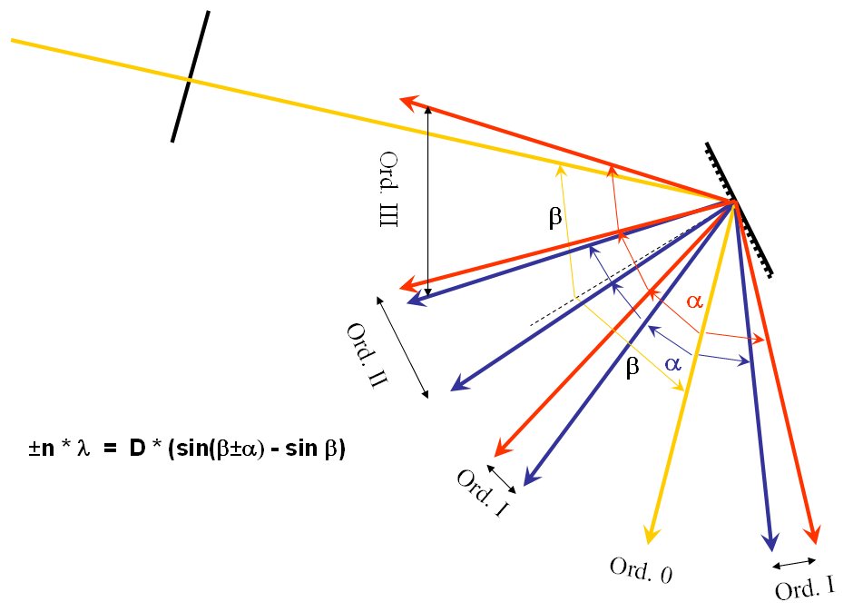
The formula on the left hand side is the general relation for a grating when the light has any arbitrary incidence angle b (taken with respect to the line perpendicular to the CDROM); and a is the deflection angle.
How this overlap shows up in second, third, and fourth order can be seen here and here.
This overlap is a principal effect and present in all grating spectroscopes. For a good spectral resolution one prefers to use higher orders, and the only way to avoid the confusion of the orders is to limit the wavelength range and to use colour filters to suppress the 'crosstalk' from the other orders. If one wants a large wavelength coverage, one has to use first or second order. This is the way astronomical spectra are taken with professional telescopes. The observer has to choose the grating's order in accordance with the project's aims.
Could one use CDs in professional spectroscopic instruments? No, not really. One can produce diffraction gratings with straight-line grooves and of much better optical quality using glass or metal as a base. And their inventor Henry A.Rowland in 1880 already produced gratings on precision curved surfaces which allowed to focus the spectra properly.
But apart from that small limitation, the optical quality of CDs and DVDs, which are designed to work with infrared lasers in your player, is very good, and one can obtain spectra of excellent quality and spectral resolution. And this can be done with any CD or DVD which had become useless because of a writing error ...
Let us end our experiments under the sun by bending the CD a little bit. The 'rainbows' change their form depending on the way we deform the CD, for example:
