Mk IV: Transmission gratings from CDs
Joachim Köppen Kiel/Strasbourg/Illkirch Spring 2007
It does happen: if the silvery surface of a piece of a CD came off, this does
not mean the end of its usefulness! Look through it at a light source:
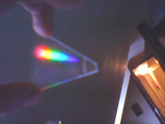
you'll see two spectra on either side of the light source. Despite the removal
of the silvery surface, the tracks are still on the transparent plastic disk!
You'll find that the spectra are not as bright as with a CDROM used in reflection,
but useful enough to make spectroscopes with such a piece!
It is easy to rip off the silvery surface, by first covering it with some adhesive
tape, pressing the tape well to the surface, and then removing the tape ... the
silvery foil comes with it.
If you have a good and powerful microscope, you should look at such a CD piece,
as you might be able to see the closely spaced
tracks. But you need about 1000x magnification.
There are several advantages of a transmission grating spectroscope from a CDROM:
- one looks nearly in the same direction as the light source
- since the spectrum is seen at an angle of about 20 degree from the light
source, one can place at that direction behind the CD a dial which
indicates the wavelengths.
although the spectra are less bright than with a CD in reflection.
The construction of such an instrument is a bit involved. Here I can
give only guidelines that allow you to design your own version.
The schema is shown below:
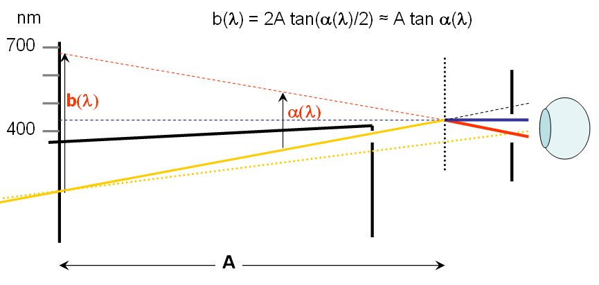
- We place the CDROM quite close to the eye, perhaps at 2 cm
- Since the first order spectrum has deflection angles of about 20°,
we place the slit on one side of the central line of the box, and
the dial on the other side.
- The length of the box gives the dimension A, and we can
use the formula shown to compute the positions of the dial marks.
You will find that these marks for equal spaced wavelengths are
almost exactly equally spaced. Thus, one needs to compute only
the wavelength scale of the dial. An even more practical approach
is to use a sliding dial or a dial plate which can be adjusted and
glued at the correct position by observing e.g. the emission lines
of a mercury vapour lamp;
this bright green emission line also seen in fluorescent lamps
is at 546 nm.
- In order to avoid the direct light from the slit reaching the
eye, it is useful to put in a baffle or a screen which completely
separates the section of the box which contains the slit from
the half which carries the dial.
- We look at the CDROM through an opening in the box. This prevents
us from looking at the direct light from the slit.
- The dial itself is a piece of cardboard into which we pierced with
a needle several tiny holes to mark the wavelengths. Thus, the light
source will also illuminate the dial marks. It is also useful to
put some diffuse plastic on the outside of the dial, as to provide
a more diffuse illumination.
Below is my finished instrument along with the design sketch which
shows the markings of the dial and the slit
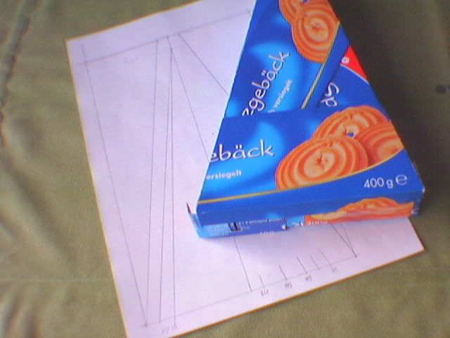
The baffle is shown here in the background, while in the right foreground
one sees the dial covered with the diffusor plastic foil
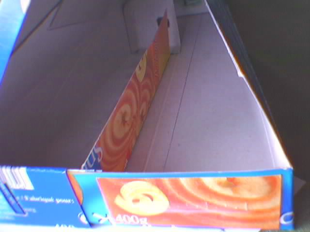
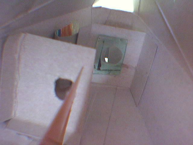
Here the baffle, the piece of CDROM, and the observer's peep-hole is seen:
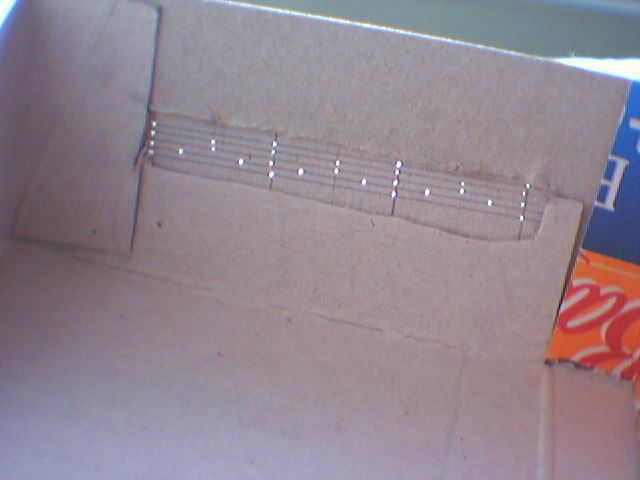
This is the dial plate seen from the inside. From left to right, four holes
mark 700, 600, 500, and 400 nm, with intervals of 50 and 25 nm indicated by
fewer holes. I did not bother to label the markings, as it would increase the
stray light in the box, and I always keep in mind which is the long wavelength
side ...
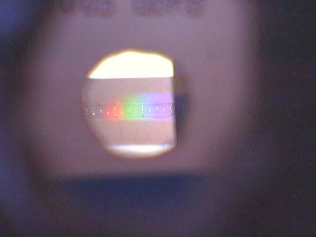
Here is a view towards the dial in the open box with the superposed
spectrum of daylight
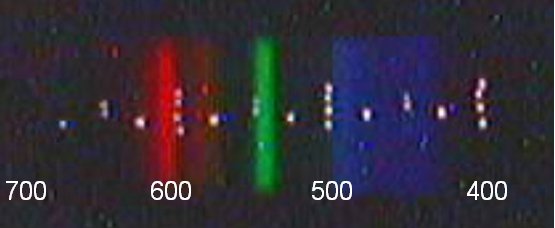
The spectrum of a fluorescent tube verifies the calibration of the dial:
| Top of the Page
| to Main Page
| to my Home Page
|


