How to calibrate the positioning system
Joachim Köppen Strasbourg 2008
The antenna dish is fully steerable in both azimuth and elevation, using two
appropriate electric motors which are powered and controlled by a controller,
which in turn communicates the current position to a computer and receives
commands to turn to a desired position.
The current positions are determined from the analogue voltages from sensors
associated with each motor. Both the analogue display of the controller and
in particular the computer program need to be calibrated in order to associate
these voltages with the true angles in azimut and elevation, which depending
on the actual orientation of the telescope mounting. This entails determination
of the zero-point as well as the range of each angular measurement.
The basic calibration of the controller and its analogue indicators
had been done by the maker of the positioning system and the ESA technicians
who installed the telescope at ISU for the first time.
The positional calibration was conceived to be done with the aid of pointing to
a TV satellite with known position, and comprises adjusting trimmer potentiometers
of the motor controller. Since this turned out to be somewhat inconvenient, we
have adopted a different approach:
- The settings in the motor controller are left as they are, but any
recalibration is done by software.
- We assume that the transformation between the angles indicated by the
motor controller and displayed by the original software are related to
the true angles by a simple linear relation:
Azimut = Offset_A + Scale_A * TrueAzimut
Elevation = Offset_E + Scale_E * TrueElevation
(That the two relations are independent of the other angle can be safely
assumed, because it had been verified that the vertical axis of the mounting
is truely vertical)
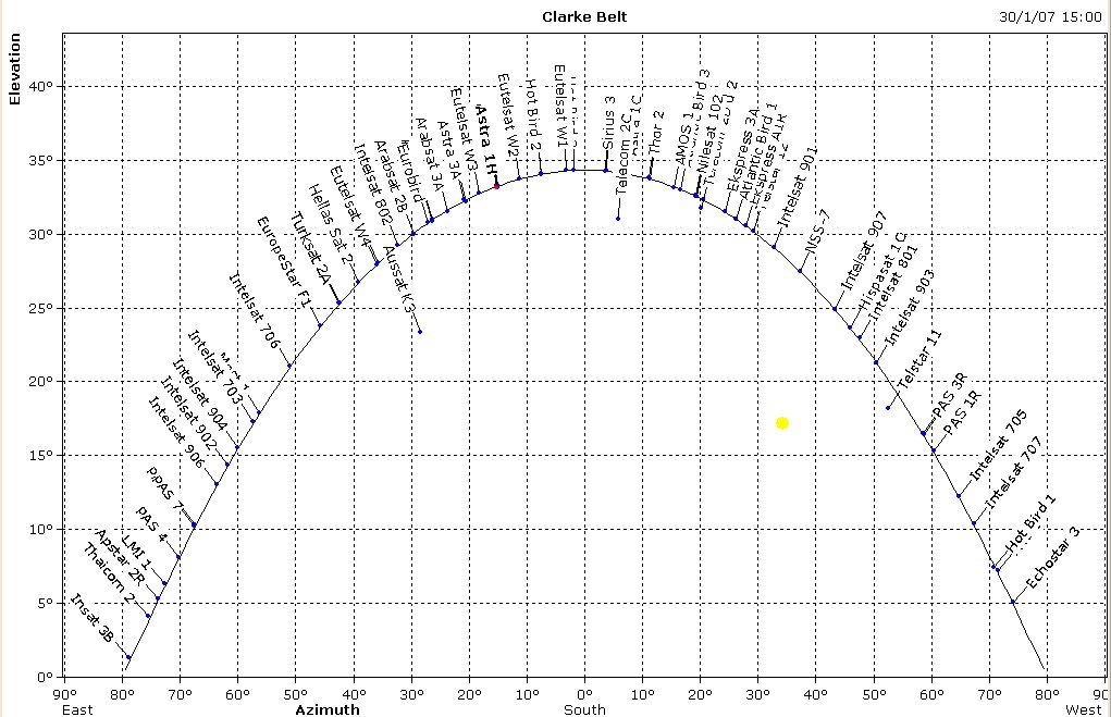
- We observe as many satellites as we can find, and determine their positions
as indicated by the computer software. Since all these geostationary satellites
must be situated in the sky on what is called the "Clarke belt", whose positions
can accurately be computed, we then simply adjust the Offset and Scale parameters
until the measured positions giv a good match to the predicted and transformed
Clarke belt. This image shows the satellites of the Clarke belt as seen from ISU,
computed for 30 Jan 2007 with the program
GorbTrack.
It also shows the
position of the Sun, the Moon is still outside the plotting area.

- The Java applet shown below is used to perform this fit. It is also used to
transform between the true coordinates and those indicated by the control software.
Thus, we use the readings from the control software as a kind of intermediate
coordinates only, based on the default settings of the software.
Hence, the software no longer needs to be calibrated. If need arises, the values
of the transformation parameters in the applet can always be modified and improved.
This JAVA applet does the transformation between the Azimuth and Elevation (as
indicated by the telescope software) and the TrueAzimuth and TrueElevation. You
enter your values and hit Return key to get the transformed values. The plot on
the right hand side shows the satellite positions as determined by us (blue dots)
and the fit of the Clarke belt (red curve, determined by the fit parameters on
the top left hand side).
For the observations of the Sun and the Moon, we can use
prediction software which produces a list of the true
positions as well as as the values of "our" transformed azimuts and elevations.
This off-line method is no longer necessary with the
New ESA-Dresden Software, installed in 2009,
because this approach is fully integrated in the program under the
calibration page.
| Top of the Page
| Back to the MainPage
| to my HomePage
|
last update: Apr. 2013 J.Köppen

