The BlackBox Receiver
Joachim Köppen Kiel 2018
The important issue in a VLF receiver is that any possible antenna (perhaps 1 m long)
will be extremely short compared to the wavelength (300 km for 1 kHz). This means that
its impedance will be highly capacitive, corresponding to a capacitor much less than
1 pF. Therefore the input impedance of the receiver must be very high, and this is
the reason that the VLF-3 receiver uses a FET as the first transistor.
Because a Darlington pair of bipolar transistors would also give a high input
impedance, I gave it a try and obtained very useful results. From that time on
I have used a Darlington pair of normal small signal silicon transistors (BC107, BC548,
2N2222, 2N3904, etc) as a emitter-follower input stage. To avoid that the bias
resistors degrade the high impedance, a 10nF bootstrap capacitor feeds the
output signal from the emitter to where the bias resistors meet, to put this
point - signal-wise - at the same level as the input.
The input circuit and the first amplifier are shown below:
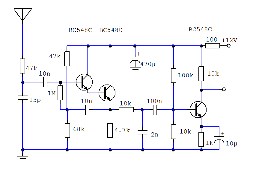 Here, a simple low-pass filter (18 kOhm / 2nF) provides some audio filtering.
I did quite a bit of experimenting with this low-pass filter as well as
with the low-pass filter in the input (47 kOhm/13 pF). The latter prevents the
direct rectification of strong AM broadcast stations. At some point, I used three
680 kOhm/13 pF combinations at the input, as is seen below:
There is one important issue about the components in the input section:
They should not show any signs of microphonics, i.e. they should not produce
any electrical noise when they are mechanically stressed. Ceramic capacitors
should be avoided, but types like those shown below are preferred:
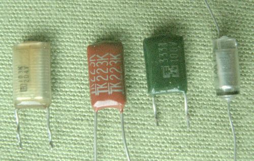 When in doubt, test by scratching the component!
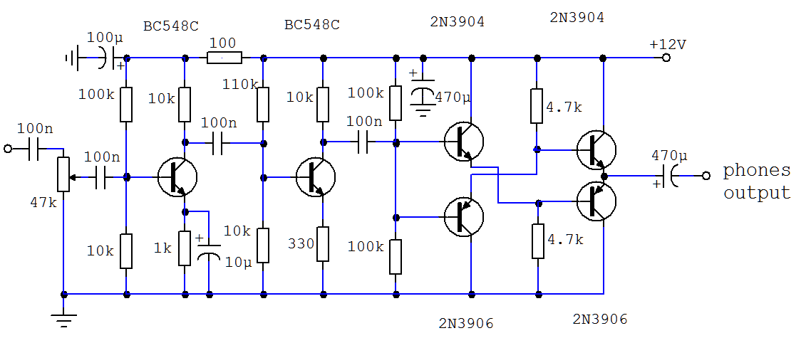
A simple audio amplifier, built from individual transistors - which overflow
my junk box - amplifies the signal to the levels necessary for the tape recorder
and the earphone. Parallel to the input of the audio amplifier, there also is
a separate trimmer potentiometer that sets the output for the tape recorder.
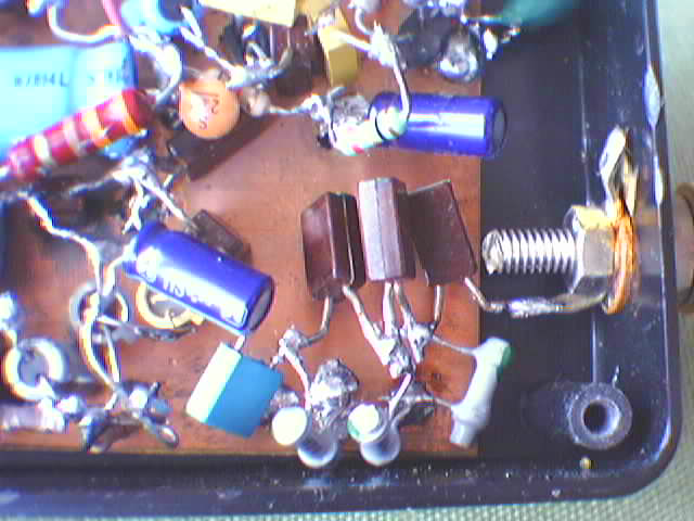
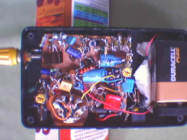
The entire receiver is built on a printed circuit board whose copper surface
acts as a ground connection. Along with the 9 V battery, it fits a small black
plastic housing:
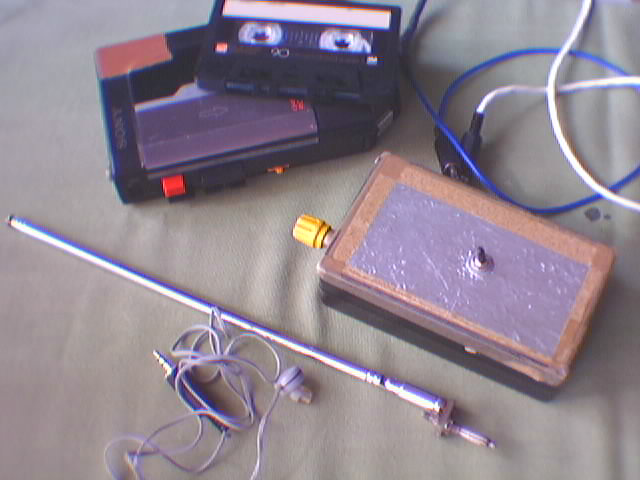
This is the complete instrumentation which accompanies me for listening
sessions on the beach. The telescopic antenna extends to about 60 cm length.
Note that the receiver's front is covered with some aluminum foil. This is
electrically connected to the receiver's ground, so that by holding the box
with my gloveless hand I provide an electric counterweight for the antenna.
This prevents feedback and whistling of the apparatus.
Furthermore, during recording sessions, I do not allow myself to move or
even to brush over my clothes (or handle plastic bags), as all these can
produce small electric discharges and hence radio noise ...
| Top of the Page
| Back to the MainPage
| to my JavaScript Tools
| to my Java Applets
| to my HomePage
|
last update: Apr 2018 J.Köppen