Go to the source code of this file.
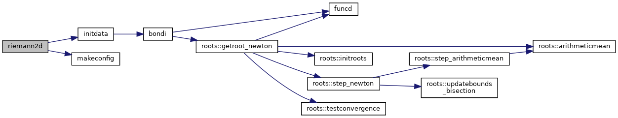
◆ initdata()
| subroutine riemann2d::initdata |
( |
class(mesh_base), intent(in) |
Mesh, |
|
|
class(physics_base), intent(in) |
Physics, |
|
|
class(timedisc_base), intent(inout) |
Timedisc, |
|
|
integer, intent(in) |
ic |
|
) |
| |
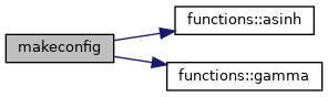
◆ makeconfig()
| subroutine riemann2d::makeconfig |
( |
class(fosite), intent(inout) |
Sim, |
|
|
type(dict_typ), pointer |
config, |
|
|
integer, intent(in) |
ic |
|
) |
| |
◆ riemann2d()
- Test:
- 19 different 2D Riemann problems for the inviscid Euler equations
- Author
- Tobias Illenseer
Test description
Numerical solutions of the inviscid Euler equations in 2D for the 19 tests proposed by Schulz-Rinne et al.
[43] . These 2D Riemann problems were also used by several other authors (
[29] ,
[27] ,
[31] ) and became a standard collection of tests for compressible flow solvers.
The test examines the shock/contact discontinuity and rarefraction wave interaction in two dimensions subdividing a quadratic computational domain into four equally sized quadrants. The computations were carried out on the unit square \( \left[-0.5,0.5 \right]\times \left[ -0.5,0.5 \right] \) centered on the origin of a planar cartesian grid. In all tests we assume an ideal gas equation of state with a constant ratio of specific heats (adiabatic index \(\gamma \)).
| Simulation parameters |
| adiabatic index | \( \gamma = 1.4 \) |
| reconstruction | conservative |
| limiter | monocent |
| diffusivity | \( \theta = 1.2 \) |
| numerical flux functions | KT (Kurganov-Tadmor) |
| boundary conditions | absorbing |
Initial conditions
The initial setup provides a distinct and constant state vector in each quadrant. To distinguish the different configurations we use the numbering scheme given in
[27] .
The panel below shows the results for the density obtained for the 19 different test cases. The resolution was always set to \( 400 \times 400 \). The diagrams were also genereted in SVG format. Thus if you want to zoom in and study the details klick on the link below.
Configuration No. 1
Configuration No. 5
Configuration No. 2
Configuration No. 6
Configuration No. 3
Configuration No. 7
Configuration No. 4
Configuration No. 8
Configuration No. 9
Configuration No. 15
Configuration No. 10
Configuration No. 16
Configuration No. 11
Configuration No. 17
Configuration No. 12
Configuration No. 18
Configuration No. 13
Configuration No. 19
Configuration No. 1 \anchor conf01
The initial condition yields four rarefactions along the interfaces of the four quadrants.
| Quadrant | Density | X-Velocity | Y-Velocity | Pressure |
| 1 | 1.0 | 0.0 | 0.0 | 1.0 |
| 2 | 0.5197 | -0.7259 | 0.0 | 0.4 |
| 3 | 0.1072 | -0.7259 | -1.4045 | 0.0439 |
| 4 | 0.2579 | 0.0 | -1.4045 | 0.15 |
Configuration No. 2 \anchor conf02
The initial condition yields four rarefactions along the interfaces of the four quadrants.
| Quadrant | Density | X-Velocity | Y-Velocity | Pressure |
| 1 | 1.0 | 0.0 | 0.0 | 1.0 |
| 2 | 0.5197 | -0.7259 | 0.0 | 0.4 |
| 3 | 1.0 | -0.7259 | -0.7259 | 1.0 |
| 4 | 0.5197 | 0.0 | -0.7259 | 0.4 |
Configuration No. 3 \anchor conf03
The initial condition yields four shocks along the interfaces of the four quadrants.
| Quadrant | Density | X-Velocity | Y-Velocity | Pressure |
| 1 | 1.5 | 0.0 | 0.0 | 1.5 |
| 2 | 0.5323 | 1.2060 | 0.0 | 0.3 |
| 3 | 0.1380 | 1.2060 | 1.2060 | 0.029 |
| 4 | 0.5323 | 0.0 | 1.2060 | 0.3 |
Configuration No. 4 \anchor conf04
The initial condition yields four shocks along the interfaces of the four quadrants.
| Quadrant | Density | X-Velocity | Y-Velocity | Pressure |
| 1 | 1.1 | 0.0 | 0.0 | 1.1 |
| 2 | 0.5065 | 0.8939 | 0.0 | 0.35 |
| 3 | 1.1 | 0.8939 | 0.8939 | 1.1 |
| 4 | 0.5065 | 0.0 | 0.8939 | 0.35 |
Configuration No. 5 \anchor conf05
The initial condition yields four contacts along the interfaces of the four quadrants.
| Quadrant | Density | X-Velocity | Y-Velocity | Pressure |
| 1 | 1.0 | -0.75 | -0.5 | 1.0 |
| 2 | 2.0 | -0.75 | 0.5 | 1.0 |
| 3 | 1.0 | 0.75 | 0.5 | 1.0 |
| 4 | 3.0 | 0.75 | -0.5 | 1.0 |
Configuration No. 6 \anchor conf06
The initial condition yields four contacts along the interfaces of the four quadrants.
| Quadrant | Density | X-Velocity | Y-Velocity | Pressure |
| 1 | 1.0 | 0.75 | -0.5 | 1.0 |
| 2 | 2.0 | 0.75 | 0.5 | 1.0 |
| 3 | 1.0 | -0.75 | 0.5 | 1.0 |
| 4 | 3.0 | -0.75 | -0.5 | 1.0 |
Configuration No. 7 \anchor conf07
The initial condition contains two rarefactions at the upper and the right interfaces and two contacts at the lower and left interfaces.
| Quadrant | Density | X-Velocity | Y-Velocity | Pressure |
| 1 | 1.0 | 0.1 | 0.1 | 1.0 |
| 2 | 0.5197 | -0.6259 | 0.1 | 0.4 |
| 3 | 0.8 | 0.1 | 0.1 | 0.4 |
| 4 | 0.5197 | 0.1 | -0.6259 | 0.4 |
Configuration No. 8 \anchor conf08
The initial condition ontains two rarefactions at the upper and the right interfaces and two contacts at the lower and left interfaces.
| Quadrant | Density | X-Velocity | Y-Velocity | Pressure |
| 1 | 0.5197 | 0.1 | 0.1 | 0.4 |
| 2 | 1.0 | -0.6259 | 0.1 | 1.0 |
| 3 | 0.8 | 0.1 | 0.1 | 1.0 |
| 4 | 1.0 | 0.1 | -0.6259 | 1.0 |
Configuration No. 9 \anchor conf09
The initial condition ycontains two rarefactions at the left and right interfaces and two contacts at the upper and lower interfaces.
| Quadrant | Density | X-Velocity | Y-Velocity | Pressure |
| 1 | 1.0 | 0.0 | 0.3 | 1.0 |
| 2 | 1.0 | 0.0 | -0.3 | 1.0 |
| 3 | 1.0390 | 0.0 | -0.8133 | 0.4 |
| 4 | 0.5197 | 0.0 | -0.4259 | 0.4 |
Configuration No. 10 \anchor conf10
The initial condition contains two rarefactions at the left and right interfaces and two contacts at the upper and lower interfaces.
| Quadrant | Density | X-Velocity | Y-Velocity | Pressure |
| 1 | 1.0 | 0.0 | 0.4297 | 1.0 |
| 2 | 0.5 | 0.0 | 0.6076 | 1.0 |
| 3 | 0.2281 | 0.0 | -0.6076 | 0.3333 |
| 4 | 0.4562 | 0.0 | -0.4297 | 0.3333 |
Configuration No. 11 \anchor conf11
The initial condition contains two shocks at the upper and right interfaces and two contacts at the lower and left interfaces.
| Quadrant | Density | X-Velocity | Y-Velocity | Pressure |
| 1 | 1.0 | 0.1 | 0.0 | 1.0 |
| 2 | 0.5313 | 0.8276 | 0.0 | 0.4 |
| 3 | 0.8 | 0.1 | 0.0 | 0.4 |
| 4 | 0.5313 | 0.1 | 0.7276 | 0.4 |
Configuration No. 12 \anchor conf12
The initial condition contains two shocks at the upper and right interfaces and two contacts at the lower and left interfaces.
| Quadrant | Density | X-Velocity | Y-Velocity | Pressure |
| 1 | 1.0 | 0.0 | 0.0 | 0.4 |
| 2 | 0.5313 | 0.7276 | 0.0 | 1.0 |
| 3 | 0.8 | 0.0 | 0.0 | 1.0 |
| 4 | 1.0 | 0.0 | 0.7276 | 1.0 |
Configuration No. 13 \anchor conf13
The initial condition contains two shocks at the left and right interfaces and two contacts at the upper and lower interfaces.
| Quadrant | Density | X-Velocity | Y-Velocity | Pressure |
| 1 | 1.0 | 0.0 | -0.3 | 1.0 |
| 2 | 2.0 | 0.0 | 0.3 | 1.0 |
| 3 | 1.0625 | 0.0 | 0.8145 | 0.4 |
| 4 | 0.5313 | 0.0 | 0.4276 | 0.4 |
Configuration No. 14 \anchor conf14
The initial condition contains two shocks at the left and right interfaces and two contacts at the upper and lower interfaces.
| Quadrant | Density | X-Velocity | Y-Velocity | Pressure |
| 1 | 2.0 | 0.0 | -0.5606 | 8.0 |
| 2 | 1.0 | 0.0 | -1.2172 | 8.0 |
| 3 | 0.4736 | 0.0 | 1.2172 | 2.6667 |
| 4 | 0.9474 | 0.0 | 1.1606 | 2.6667 |
Configuration No. 15 \anchor conf15
The initial condition contains two contacts at the lower and left interfaces, a rarefaction at the upper and shock at the right interface.
| Quadrant | Density | X-Velocity | Y-Velocity | Pressure |
| 1 | 1.0 | 0.1 | -0.3 | 1.0 |
| 2 | 0.5197 | -0.6259 | -0.3 | 0.4 |
| 3 | 0.8 | 0.1 | -0.3 | 0.4 |
| 4 | 0.5313 | 0.1 | 0.4276 | 0.4 |
Configuration No. 16 \anchor conf16
The initial condition contains two contacts at the lower and left interfaces, a rarefaction at the upper and shock at the right interface.
| Quadrant | Density | X-Velocity | Y-Velocity | Pressure |
| 1 | 0.5313 | 0.1 | 0.1 | 0.4 |
| 2 | 1.02222 | -0.6179 | 0.1 | 1.0 |
| 3 | 0.8 | 0.1 | 0.1 | 1.0 |
| 4 | 1.0 | 0.1 | 0.8276 | 1.0 |
Configuration No. 17 \anchor conf17
The initial conditioncontains two contacts at the upper and lower interfaces, a shock at the left and rarefaction at the right interface.
| Quadrant | Density | X-Velocity | Y-Velocity | Pressure |
| 1 | 1.0 | 0.0 | -0.4 | 1.0 |
| 2 | 2.0 | 0.0 | -0.3 | 1.0 |
| 3 | 1.0625 | 0.0 | 0.2145 | 0.4 |
| 4 | 0.5197 | 0.0 | -1.1259 | 0.4 |
Configuration No. 18 \anchor conf18
The initial condition contains two contacts at the upper and lower interfaces, a shock at the left and rarefaction at the right interface.
| Quadrant | Density | X-Velocity | Y-Velocity | Pressure |
| 1 | 1.0 | 0.0 | 1.0 | 1.0 |
| 2 | 2.0 | 0.0 | -0.3 | 1.0 |
| 3 | 1.0625 | 0.0 | 0.2145 | 0.4 |
| 4 | 0.5197 | 0.0 | 0.2741 | 0.4 |
Configuration No. 19 \anchor conf19
The initial condition contains two contacts at the upper and lower interfaces, a shock at the left and rarefaction at the right interface.
| Quadrant | Density | X-Velocity | Y-Velocity | Pressure |
| 1 | 1.0 | 0.0 | 0.3 | 1.0 |
| 2 | 2.0 | 0.0 | -0.3 | 1.0 |
| 3 | 1.0625 | 0.0 | 0.2145 | 0.4 |
| 4 | 0.5197 | 0.0 | -0.4259 | 0.4 |
References
- [43] C. W. Schulz-Rinne et al.: Numerical Solution of the Riemann Problem for Gas Dynamics, SIAM J. Sci. Comp. 14 (1993), 1394-1414
- [29] P. Lax, X.-D. Liu: Solution of Two-dimensional Riemann Problems of Gas Dynamics by Positive Schemes, SIAM J. Sci. Comp. 19 (1998), 319-340
- [27] A. Kurganov, E. Tadmor: Solution of Two-Dimensional Riemann Problems for Gas Dynamics without Riemann Problem Solvers, NMPDE 18 (2002), 561-588
Definition at line 465 of file riemann2d.f90.


