At 21 cm and for our small telescope, we may neglect the emission from the sky: Tsky = 0. Hence we can express the system temperature as
However... it isn't all that simple: the thermal emission from the Earth atmosphere plays quite an important role in the background noise, particularily at lower elevations. See Flux Calibration and System Temperature and How to Interpret Measurements for a more comprehensive treatment!
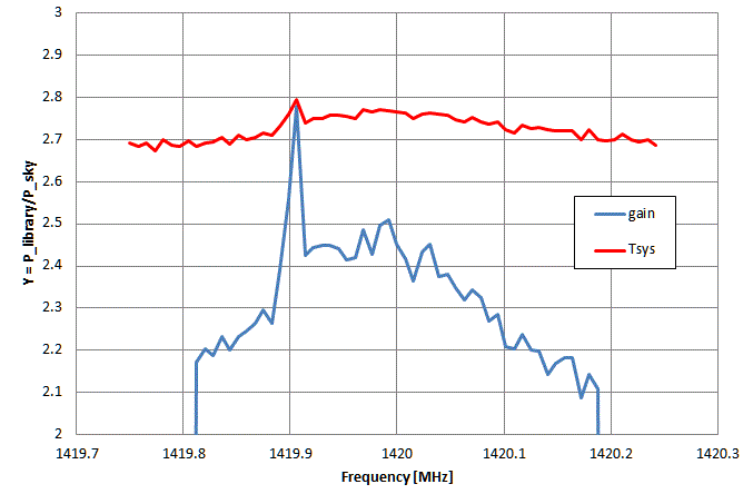
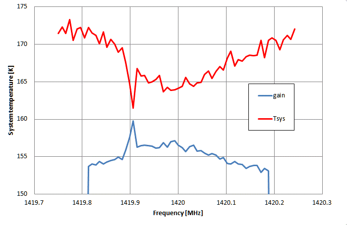
The simplest, easiest, but also the most fundamental way is to use the wall of our library as a calibration source: it fills the entire antenna beam and we may well assume its physical temperature to be close to 290 K - if we required a higher accuracy, we could use a thermometer to measure it. We measure with a wide frequency span the spectrum of the library wall - our Stow sposition - and then at some sky position, such as AZ=1° EL=60°. From the recorded spectra we compute Y and then the system temperature and plot them as a function of frequency:
On the first day of our operations, we did a complete solar observation and determined the system temperature:
- since our counts (cts) are strictly proportional to the power, we can determine Y = Stow/Sky = 3599/1318 = 2.73 (or 4.4 dB) from averaging over the spectrum
- this gives a system temperature of 168K (which is the value we should expect from the manufacturer's information)
- for the Sun we get Y = Sun/Sky = 5180/1318 = 3.933 (or 5.9 dB)
- this gives an antenna temperature of the Sun: 490 K


We may go one step further:
- We know the power received from the Sun in absolute terms Psun = 2 k Tsun with Boltzmann's constant k = 1.38 E-23 Ws/K. The factor of 2 takes into account that the solar emission is unpolarized, but the antenna measures only one polarization state. Using more convenient units for radio astronomy (1 Jansky = 1 Jy = 1E-26 Ws/mē) we get Psun = 2760 Tsun = 1352400 Jy mē = 135 SFU mē (solar flux units)
- Our antenna of diameter 2.3m has a geometrical cross section of 4.15 mē, hence the measured solar flux would be 135/4.15 = 32.5 SFU
- However, from NOAA we know the solar flux measured by professional stations on that day on 1415 MHz as 54 SFU.
- Consequently, we can compute the efficiency of our telescope as 32.5/54 = 0.6. This means that the effective collecting surface of the telescope is only about 2.5m, which corresponds to an effective diametre of 1.8m. These figures are well in agreement of what one can expect. Perhaps some optimization of the antenna could improve these numbers somewhat.
This first measurement was before the growing interference became so severe, that we had to install narrow band filters in front of the preamplifier. The inevitable insertion loss of the filters degrades the telescope's performance. The best system temperature reached so far is about 300 K. But we successfully surveyed the emission of the Milky Way even with system temperatures of 1000 K!
| Top of the Page | Back to the MainPage | to my HomePage |
last update: Oct 2020 J.Köppen